Caterpillar Custom Track Service Handbook Page 252
Service Handbook
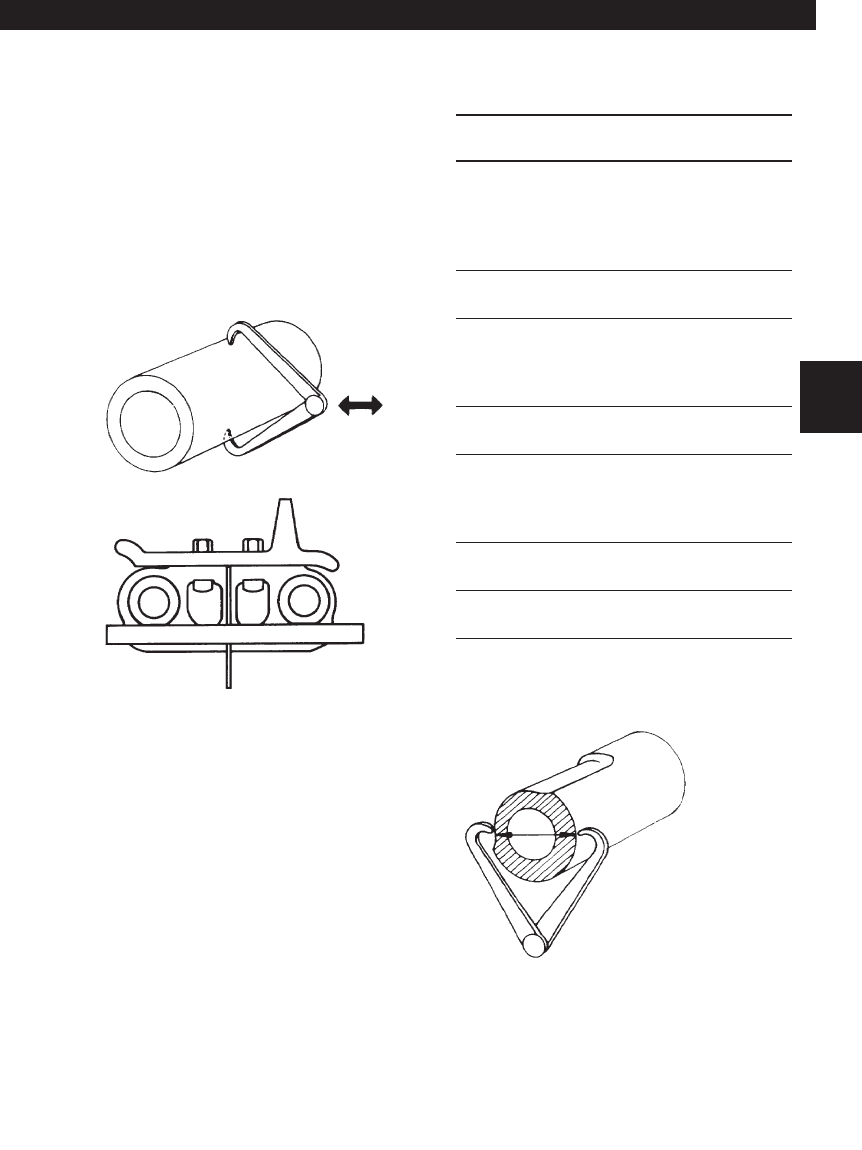
Wear Patterns — See pages 29 through
32 for a detailed discussion of link wear
patterns.
Split Master Links — Use the assembly
procedures on page 33 for split master
links. Refer to “Shoes” on the following
page for bolt torque specifications.
Bushing — Sealed &
Lubricated Track
Measurement — Use the caliper, depth
gauge or Ultrasonic Wear Indicator to
measure the vertical position to the closest
0.01" (0.25 mm). The vertical position is
expected to be the most worn position for
Sealed and Lubricated Track bushings on
low sprocket machines. Measurement of
other wear positions can be made, but are
not expected to be critical.
Bushing Allowable Wear — Bushing
allowable wear is based on the remaining
strength to resist cracks. For high impact
underfoot conditions use lesser allowable
wear. For low impact use greater allow-
able wear.
Dry Joints
See page 42 for dry joint inspection proce-
dures and recommended service. If a dry
joint is found, measure pitch extension
over that one joint. Schedule service if the
pitch exceeds these limits:
New Track Single Joint
Model Pitch Wear Limit
D3 6.125" (155.6 mm) 6.50" (165 mm)
D4
931
933
935
D4 6.75" (171.5 mm) 7.25" (185 mm)
941
D5 6.91" (171.5 mm) 7.50" (190 mm)
951
955
561
D6 8.00" (203.2 mm) 8.67" (220 mm)
955
D7 8.50" (215.9 mm) 9.12" (321 mm)
977
571
572
D8 9.00" (228.7 mm) 9.75" (250 mm)
983
D9 10.25" (260.4 mm) 11.00" (280 mm)
594
Bushing — Sealed Track
— External
Measurement — To measure external
wear use the caliper or the Ultrasonic Wear
Indicator. Measure the minimum diameter
regardless of the position (vertical, forward,
reverse). See details on measurement pro-
cedures, page 44.
251
COMPONENTS
Low Sprocket Machines
05.Low(246-325) 7/11/03 3:52 PM Page 251
Contents Summary of Caterpillar Custom Track Service Handbook
- Page 1Custom Track Service Handbook CUSTOM TRACK SERVICE 15th edition
- Page 2CATERPILLAR ® CUSTOM TRACK SERVICE HANDBOOK 15th EDITION © 1971, 1973, 1974, 1976, 1977, 1979, 1982, 1985, 1987, 1989, 1991, 1993, 1998, 2003 Caterpillar, Inc. ® Printed in U.S.A. PEKP9400-03 1
- Page 3I. General Information Measurement Tools .......................................................................8 Variables That Affect Undercarriage Life Controllable Variables ........................ ........................................11 Non-Controllable Variables .................. ........
- Page 4IV. Low Sprocket Machines Management ............................................................................248 Genuine Cat® Undercarriage D3, D4B, D4C, D4G, 931, 933, 935 ...............................................258 D4, D4D, D4E, 941 ..................... ................................
- Page 5E70B.......... ...........................................................................710 E110B, E120B ..........................................................................720 E140 .......... ...........................................................................728 E180, EL180 ........
- Page 6Edition Fifteen is a comprehensive update to the CTS Handbook. Nearly every wear chart in the book was updated. The General Information section, the Management & Merchan- dising section and the Management section of the four product types were also updated. Some of the changes you will notice includ
- Page 7
- Page 8General Information 7
- Page 9MEASUREMENT TOOLS 6V9413 CTS Tool Kit Separate Tools Part Number Description Use 6V7784 CTS Pouch Carrying Tools 8H8580 Scraper Cleaning U/C Components 5P3920 12" Steel Rule With Caliper And Depth Gauge 4S9404 4" Caliper Bushing O.D. 8T7790 6" Caliper D11N, D11R Bushing O.D. 4S9405 12" Caliper Rolle
- Page 10MEASUREMENT TOOLS 168-7720 Ultrasonic Wear Indicator III Group Separate Tools Part Number Description 168-7720 Ultrasonic Wear Indicator III Group 168-7721 Ultrasonic Wear Indicator III 168-7722 Ultrasonic Probe 9U-7981 Couplant 4C-5490 Couplant Holder 6V-7145 Case (without foam insert) 4C-4772 Foam
- Page 11MEASUREMENT TOOLS Ultrasonic Wear Indicator The ultrasonic wear indicator measures component thickness by sending high frequency sound waves through the material to be measured. The elapsed time between sending and receiving the sound waves allows the tool to determine thickness. This electronic CTS
- Page 12UNDERCARRIAGE LIFE VARIABLES — CONTROLLABLE VARIABLES Variables That Affect effect on the operation of undercarriage Undercarriage Life systems. Track adjustment can have a very large The variables that determine complete effect on external bushing life, even to the undercarriage system life and wea
- Page 13SHOE WIDTH Shoe Width For Undercarriage System Wear Track-type Machines and Structural Life Factors Track shoe width and degree of impact Shoe Wear Life (bumpiness) can affect the wear life of the Wider shoes do not improve wear life. The undercarriage. Since shoe width is a con- extra wear material
- Page 14SHOE WIDTH The following chart shows the effect of Sealed and Lubricated track link assembly bending stresses as Track Joint Life shoe width increases. The most costly effect of too wide shoes in 100 high impact conditions and/or steep terrain is the loss of lubricant and seal life result- 80 ing in
- Page 15ALIGNMENT Alignment for all Track Type Machines improper alignment of one or more parts excluding *D9R (SN 7TL1212-up and of the roller frame, idlers or sprocket. 8BL1422-up) *D10R (SN 3KR1331-up) and Complete discussion on checking and *D11R (SN 9TR202-up and 9XR154-up). measuring roller frame alig
- Page 16ALIGNMENT Bow Similar to toe-in and toe-out, but roller frame is bent and curves in or out with respect to tractor. CAUSE: bent roller frame EFFECT: similar to toe-in and toe-out except rear rollers are not affected REMEDY: straighten roller frame Twist When viewed from the front, the roller frame i
- Page 17ALIGNMENT Lateral Displacement When viewed from top, idler is parallel to, but moved toward or away with respect to the tractor and roller frame. CAUSE: improper shimming EFFECT: wears inner or outer idler flanges and inner rail sides selectively and may affect front roller(s) if severe REMEDY: corr
- Page 18ALIGNMENT Lateral Displacement When viewed from top or rear, sprocket is parallel to but moved in or out with respect to tractor and roller frame. CAUSE: sprocket not pressed proper dis- tance onto shaft EFFECT: inboard or outboard sprocket sides and rail insides worn selectively, may affect rear ro
- Page 19VIBRATION Track-Excited Vibration and fall in unison with each scallop as they pass over the links, thus creating vibration. Track-excited vibration is the most widely Two factors, machine speed and the depth encountered vibration on track-type ma- of the scallops, affect the amount of vibra- chines
- Page 20VIBRATION • Checking the Balance of the Machine • Adjusting the Height of Center Tread Idlers Procedure to Determine Idler Height (D8L, D8N, D8R, D9L, D9N, D10, D10N, D11N Tractors) Illustration 1. Idler Height. Under typical operating conditions, wear causes the diameter of the track roller treads
- Page 21VIBRATION 2. To check front idler height, carefully move the machine in REVERSE until a track shoe grouser is directly below the center of the idler shaft. See Illustration 2. 3. Measure the distance (dimension X), between the bottom of the track shoe grouser in full contact with the surface and the
- Page 22NON-CONTROLLABLE VARIABLES — UNDERFOOT CONDITIONS Non-Controllable Variables experience, but you should be aware of the possibility. There are a number of variables that affect Usually, the link is the best component to rates and patterns of wear which cannot be use for comparing overall relative ab
- Page 23UNDERFOOT CONDITIONS Wide shoes accentuate the effects of Packing Materials impact conditions. Machines with single grouser shoes are more susceptible to A Extrudable (when wet) higher impact effects than those with Sanitary Landfill (garbage) lower profile or multi-grouser shoes. Silt soils Clay so
- Page 24UNDERFOOT CONDITIONS 3. Mud and snow sprockets and segments Chemicals should only be used in the constant Corrosive chemicals found in nature plus presence of soft extrudable packing man-made compounds may have the effect materials. In any other material they of either eating away at wear material o
- Page 25UNDERFOOT CONDITIONS Terrain Conditions All application effects are influenced by the terrain on which the work is being done. The most common effects are described here regardless of the degree of impact, or the operating condition. Working Uphill Shifts weight balance to the rear causing relativel
- Page 26PARTIALLY CONTROLLABLE VARIABLES Application Conditions what the machine operator is doing. These operator induced variables may or may not The word “applications,” often misused to be a function of the underfoot conditions, describe underfoot condition, should be the type of machine or even the app
- Page 27PARTIALLY CONTROLLABLE VARIABLES Preferred-Side Dozing or Other Work Wear rates on the loaded side of a dozer will increase on all components if only one side of the machine is used. Wear rates increase as more power is applied to the loaded side. More slippage and packing will occur on the loaded s
- Page 28PERCENT WORN CHARTS Components In most cases, service limit projections made from less than 30 percent worn can Each component has individual measure- not be considered accurate. However, such ment techniques, wear limits, wear charts, projections can be used to determine call rebuildability criteri
- Page 29LINKS Link Rail Wear Wear Limits Link wear limits are determined by setting Measurement Technique the allowable wear equal to some fraction Track links may be measured by the depth of the clearance between the link and the gauge or by the ultrasonic wear indicator. roller. On some machines this clea
- Page 30LINKS 3. Rail side wear due to roller flange or Sealed and Lubricated Track vs. guiding guards or inside rail gouging Sealed Track — track link effects by the sprocket hasn’t reduced rail Due to the expected absence of internal width significantly. wear, counterbore depth and elongation 4. Pin boss
- Page 31LINKS Rail Side Wear (inside and/or outside) Uneven (Scalloping) Wear CAUSES: Rolling and sliding contact on Rail Top with roller and idler flanges. CAUSES: No. 1 & 3: Faster wear rate due to ACCELERATED BY: Same as “Rail Top reduced contact with rollers at narrower link Wear” plus uneven terrain, t
- Page 32LINKS Elongation of Counterbore Pin Boss Tip Worn CAUSES: Rotating contact with the CAUSES: Sliding and roller contact with bushing end in pitch extended Sealed roller flange tops (see roller flange wear). Track (see Sealed Track bushing counter- ACCELERATORS: Nonuniform front to bore wear). rear ro
- Page 33LINKS Pin Boss End - Guiding Guard Wear Link Cracking CAUSES: Sliding contact between pin CAUSES: Repeated twisting of link. boss ends and guiding and roller guards. ACCELERATORS: Same as “Rail Spall- ACCELERATORS: Same as rail side wear. ing” plus degree of rail material worn EFFECT: Reduces pin re
- Page 34LINKS NOTE: Links in Sealed and Lubricated Assembling and Torquing Track should generally experience Procedure reduced pin and bushing bore enlarge- ment and subsequent retention loss. This is The importance of proper assembly due to the absence of internal wear, which sequence and torquing cannot b
- Page 35LINKS Former Link Service Limits These former links do not appear on the wear chart pages. But, by using this procedure and chart, you can calculate the percent worn measurement. STEP 1 STEP 2 New Link Height - Worn Link Height = Amount Worn Amount Worn Allowable Wear x 100 = Percent Worn Track Link
- Page 36LINKS Track Link New Link Allowable Model Pitch Part Number Height Wear Service D7 8.00" 1S1863 & 64 4.62" .38" 4.24" (203.2 mm) 1S6433 & 34 (117.5 mm) (9.7 mm) (107.5 mm) 8.00" 7M6763 & 64 4.50" .38" 4.12" (203.2 mm) (114.3 mm) (9.7 mm) (104.6 mm) 8.00" 2M7265 & 66 4.50" .38" 4.12" (203.2 mm) (114.
- Page 37SEALED & LUBRICATED TRACK PINS & BUSHINGS Sealed and Lubricated Track Bushing Wear Measurement Technique The track bushing is the most important component in the undercarriage to measure and interpret accurately. To do this, three measurement methods are available, each using tools provided in the C
- Page 38SEALED & LUBRICATED TRACK PINS & BUSHINGS (D) Bushing not Cleaned Well Before Measurement — If the bushing surface is not cleaned the measurement taken will be oversized. (E) Calipers Not Placed at Most Worn 2. Depth Gauge Method Portion of Bushing — If the caliper The method for measuring the verti
- Page 39SEALED & LUBRICATED TRACK PINS & BUSHINGS Advantages of the “greater allowable wear” are provided in Depth Gauge Method bushing wear charts. At 100 percent worn, (A) Absolutely insures vertical position is the lesser allowable wear column pro- being measured (unless measured at a vides more bushing
- Page 40SEALED & LUBRICATED TRACK PINS & BUSHINGS Sealed and Lubricated Track vs Life after dry turn cannot be expressed Sealed Track Effects as a percent of wet life before turn. It will Due to expected absence of internal wear most closely approximate life after turn the Sealed and Lubricated Track bushin
- Page 41SEALED & LUBRICATED TRACK PINS & BUSHINGS EFFECT: (1) Vertical position should overtake either pocket as most worn position in later hours if track is properly adjusted and new segments are not installed prematurely. (2) Track may jump on sprocket if sprocket tooth tip height is worn excessively and
- Page 42SEALED & LUBRICATED TRACK PINS & BUSHINGS Roller Flange Wear CAUSES: Track Rollers inner flanges Bushing Cracks (Through the wall) and/or carrier roller flanges contacting CAUSES: Exceeding wear limit for respec- bushing due to one or more of (a) links (b) tive degree of impact or other criteria. ca
- Page 43SEALED & LUBRICATED TRACK PINS & BUSHINGS Dry Sealed and Lubricated Track Joints Premature dry joints in Caterpillar Sealed and Lubricated Track may be detected by any of the following methods: 1. Hand feeling for relatively warm bush- ings (or pin ends) after the machine has been operating. 2. Meas
- Page 44SEALED & LUBRICATED TRACK PINS & BUSHINGS Pin Breakage Pin End Wear CAUSES: Crack starts on outer surface CAUSES: Sliding contact with track guid- and spreads through entire pin at a fast rate ing and/or roller guards and/or rocks. (not nearly as common as with Sealed (May be seen on either or both
- Page 45SEALED TRACK PINS & BUSHINGS Sealed Track Bushings Wear Wear Limits As mentioned above, wear limits for In early hours, the wear patterns on Sealed Sealed Track bushings are determined not Track bushings should be very similar to only on the basis of remaining strength those shown for Sealed and Lub
- Page 46SEALED TRACK PINS & BUSHINGS External Wear Early hour wear pattern in Sealed Track bushings are similar to those for Sealed and Lubricated Track due to little or no internal wear. Shown here are typical wear patterns for late hour normal conditions where internal wear has begun to have a measurable
- Page 47SEALED TRACK PINS & BUSHINGS Other Wear Patterns — Disassembled Track Forward and Reverse Drive Sides Critical Compared to Vertical (30° to 60° from vertical) CAUSES: Sliding motion of bushing against Bushing End Wear sprocket under abnormal interference loads CAUSES: Sliding contact between inside
- Page 48SEALED TRACK PINS & BUSHINGS Bushing — Link Counterbore Wear Bushing Cracks (Through the entire wall) CAUSES: Rotational sliding contact with link counterbore and abrasives (always a CAUSES: Exceeding internal wear limit result of internal wear pitch extension). and/or exceeding external wear limit
- Page 49SEALED TRACK PINS & BUSHINGS Bushing Loose in Links Wear Limit and Percent Worn Chart See “Sealed and Lubricated Track Bush- The wear limits and wear charts for internal ing Structural Problems.” wear include only the 0.12" (3.1 mm) lesser allowable wear. Since “destruction point,” as related to Sea
- Page 50SEALED TRACK PINS & BUSHINGS Wear and Structural Problems be seen at either or both ends of pin — on Sealed or Dry Track Pins usually more severe on outboard side). ACCELERATORS: Uneven terrain, and side hill operation. Too-wide shoes, worn rolling component flange misalignment and snaky track are m
- Page 51SEALED TRACK PINS & BUSHINGS replaced. The general guidelines discussed in the section entitled “Track Manage- ment” should be understood and practiced before applying these specifics. 1. If a Sealed Track pin and bushing turn and/or replacement is required to help utilize total track link life it s
- Page 52SHOES Grouser Wear of the grouser bar. In this case, a depth gauge will be required to determine per- Measurement Technique cent worn. Grouser wear is the only measurable Wear Limits wear position on the shoe for which limits Wear limits for all shoes are based on and percent worn charts are provide
- Page 53SHOES Track Shoe Cause and Effect Leading Edge Performance Shoe wear and structural life is more affected by soil and underfoot conditions plus operating conditions than any other component in the undercarriage. So, wear Trailing Edge rate and structural problems are good indi- Plate cators of soil
- Page 54SHOES Shoe Structural Problems EFFECTS: Loss of unused shoe wear life; loss of shoe regrouserability; damage to All shoe structural problems described link bolt holes and resulting loss of wear here should be considered for their own life and rebuildability. cause plus for the transferred effect int
- Page 55SHOES These Machine U/C System Wear & Structural ... Productivity Factors Life Factors As Flotation Penetration Maneuver- Versatility Shoe Shoe Pin & Link & these Traction ability Bushing Rollers increase . . . W.L. S.L. W.L. & S.L Com W.L. & S.L. Shoe Width ⇑ ⇒ ⇓ ⇒ ⇓ ⇓ (grouser & plate) Shoe Sectio
- Page 56SHOES 2. Lubricate the bolt threads and bolt washer faces. 3. Tighten the bolts to the specified torque. 4. Give each bolt an additional 1/3 turn. Initial torque draws the parts together tightly. An additional 1/3 turn gives the bolt proper stretch for good retention. Stretching stresses the bolt un
- Page 57IDLERS Idler Wear Wear Limits Idler tread allowable wear and resulting Measurement Technique wear limits are based on two basic criteria: Tread and center flange wear are the mea- Rebuildability of the tread surface plus surable wear positions on idlers. center flange to track bushing clearance. As
- Page 58IDLERS Idler Wear Patterns Idler wear patterns can be used to help interpret abnormal wear causes on mating parts, track links, plus interpret other con- trollable and non-controllable accelerator variables, which may be affecting non- mating parts such as rollers which are harder to see and inspect
- Page 59IDLERS Idler Position Some tractors have two-position idlers which can be adjusted to provide either “high” or “low” idler position. With the idlers in the “high” position, there is less track-to-ground contact area, and the tractor is more maneuverable. With the Flange Top Wear idlers in the “low”
- Page 60CARRIER ROLLERS Carrier Roller Tread Wear Measurement Technique Carrier roller tread wear may be measured by the large caliper or by the ultrasonic wear indicator. The ultrasonic wear indicator does not measure cast iron so the carrier rollers on some D3, D4, D5, D6 and 225 machines may need to be m
- Page 61CARRIER ROLLERS Swapping Carrier Rollers Carrier rollers can be swapped from front to rear and left to right to help balance their wear life in cases where conditions have caused unequal wear rates. Criteria are: greater than 1.5:1 ratio and average less than 60 percent worn. Uneven Flange Side Wear
- Page 62TRACK ROLLERS Roller Tread Wear Track roller wear is the most difficult of all to measure and interpret. In some cases not all measurements will be possible. Several assumptions and correlations may have to be made to better interpret the roller system wear condition in the absence of complete Corre
- Page 63TRACK ROLLERS All these errors are similar to errors and measuring can be done anywhere on the results made when measuring track bushings. surface of the roller). On low sprocket track-type tractors, former track-type loaders, and excavators, the retainer bolts are not visible. For these rollers, ob
- Page 64TRACK ROLLERS Pin boss to roller flange interference ACCELERATORS: Weight, horsepower, results in wear on top of roller flanges, machine speed, impact, abrasiveness, and thus reducing the rebuildability and to some extent packing. Terrain and appli- strength of the flanges. cation often determine un
- Page 65TRACK ROLLERS Roller Swapping Due to the expected unbalanced wear rate between rear, front and center rollers under many conditions, it’s often desirable to swap rollers to and from front and/or rear positions to center position midway through their average wear lives. One con- venient time for this
- Page 66TRACK ROLLERS Rules Recap 1. Swap rollers if percent worn of most worn exceeds percent worn of least worn by more than 1.3:1 ratio. 2. Swap rollers when the average percent worn is close to 50 percent (or 60 per- cent if target is destruction). 3. Swap most worn with least worn of same flange type;
- Page 67SPROCKETS Sprocket Wear The gauge should be placed into one or more teeth with the point at the root aimed It is recommended to replace sprocket at the center of the sprocket. segments at bushing turn time or track If the point of the gauge touches the tooth replacement. root, the sprocket tooth doe
- Page 68SPROCKETS Sprocket Wear Patterns The new sprocket reuse gauge makes interpretation of sprocket tooth profile wear patterns much easier. Also, sprocket wear patterns should now be used only to help determine the cause and effect of cor- responding bushing wear patterns since the gauge will indicate s
- Page 69SPROCKETS CAUSES: Sliding contact with corre- more than 1" (3/4" on one carrier roller sponding bushing position. With Sealed machines) of slack results in “back jam- and Lubricated Track it indicates moderate ming” the bushing at the bottom of the degree of packing. With Sealed Track it sprocket in
- Page 70SPROCKETS Sprocket Side Wear And Corner Forward Drive Side Tip Wear Wear or Gouging CAUSES: Bushing sliding interference (Inner and/or Outer) due to mislocation of bushing in very CAUSES: (1) If inner or outer sides are severe packing with Sealed and Lubricated over 360° of sprocket, principal cause
- Page 71SPROCKETS Mud & Snow Segments How to Properly Torque and Rims Segment Hardware The principal cause of segment loosening, and subject loss and/or damage to other parts, is improper torque-turn tightening method. To install segment hardware, first, lubri- cate the bolt threads and the washer face of t
- Page 72GUARDS Guiding Guard Wear Roller guards should not be used therefore in any condition where there is no danger of rocks and debris entering the spaces between the rollers and causing roller, link, bushing or sprocket structural damage. Roller guards should be considered when working in the following
- Page 737
- Page 74Management & Merchandising 73
- Page 75TRACK MANAGEMENT Introduction to Track When running to destruction, it is impor- Management tant to leave the parts on the machine as long as possible to minimize the cost per Track management objectives: hour. Use the following guidelines when 1. Match pin and bushing life with link performing an u
- Page 76TRACK MANAGEMENT Track Seal Replacement Post Turn Seals Recommendations This type of seal, introduced first on the D11, was designed for use during a pin & Good track seal maintenance practices bushing turn or track reseal. Post Turn assure maximum life for tracks. Use the Seals are smaller in diame
- Page 77TRACK MANAGEMENT Crescent Track Seals (noncurrent) Always reuse crescent track seals at This type of seal provides adequate seala- bushing turn time. bility. Reuse crescent seals because of established wear patterns between the seal and the end of the bushing. CTS Inspection Report The Custom Track
- Page 78TRACK MANAGEMENT How to Fill-Out CTS Inspection 4. Calculated Data — Hours on Wear Report Using Caterpillar Form Surface is very important data and may as Example* be calculated by subtracting the hours 1. Customer and Machine Information or date installed from the current hour meter reading. Withou
- Page 79INSPECTION REPORT 1 3 2 4 4 78
- Page 80CALCULATIONS Calculations Example: The object of CTS calculations is to 2000 SMU x 1.2 = 2400 SMU project time remaining on components to (total potential to 120% worn) their 100 percent worn (service point) 5. Find the hours left on the part until it and/or 120 percent worn. Simply deter- would rea
- Page 81INSPECTION REPORT 80
- Page 82TOTAL LIFE SCALE The Total Life Scale SH — percent Track Shoe percent worn to Service Limit A Total Life Scale provides a simple, I — percent Idler(s) percent worn convenient, way of expressing the measured to Service Limit (Use symbol and calculated values from the CTS inspec- below Total Life Scal
- Page 83TOTAL LIFE SCALE Maintenance/Rebuild/Replace (REP) — Pin and Bushing or Bushing Action Symbols and Seal Replacement (M) — Measurement or Inspection (SEG) — Segment Replacement Point (REG) — Regrouser Shoe (T) — Sealed Track Pin and Bushing ////// — Unutilized Link or other major Turn component life
- Page 84RECONDITIONING & DESTRUCTION LIFE Reconditioning and Destruction Life, as a Percentage of Original Life to Service Point Additional Life if Original Life Reconditioned Liferun to destruction to Service Point to Service Point (As % of life to (Actual or Projected) (As % of Original) service Point) Li
- Page 85UNDERCARRIAGE MANAGEMENT Summary of Pin / Bushing to Link Ratios Pin/Bushing Critical Actions to be Taken Item to Link % Sealed & Lubricated Worn Ratios Sealed Link Assembly Link Assembly Less than 1:1 ratio Treat like 1:1 (Sealed & Treat like 1:1 ratio - will Lubricated Track may not provide bushin
- Page 86TOTAL LIFE SCALE Diagraming a Total Life Scale The normal sequence of steps to diagram a Total Life Scale is shown below: 1. Choose an hour or life interval which will allow the entire potential undercarriage life to be shown. To determine the length, project the life of the least worn (longest life
- Page 87TOTAL LIFE SCALE The following example demonstrates the possible use of Total Life Scales when comparing the above Sealed Track and Segment wear life and maintenance history with 3 alternative projected Sealed and Lubricated Track wear life and maintenance expecta- tions in identical conditions: Sea
- Page 88COST PER HOUR Total Cost Per Hour 4. Cost of hardware related to installation and removal The most important information a Product Support Representative has to help the Indirect Costs user manage his undercarriage investment (Usually hard to document) is Total Cost Per Hour comparisons 1. Downtime
- Page 89COST PER HOUR The link life to service point and destruction point is shown for reference purposes only and is not included in the cost per hour comparison. a. Single grouser shoe run to destruction and replaced twice to equal link: x SS x SS LD SG S SD SD x REP SD REP SCRAP b. Extreme service shoe
- Page 90COST PER HOUR Total Cost Per Hour In the previous example we compared only the shoe portion of the cost per hour of the track group. Since the link life was a factor in the total effective life of the shoes it may be desirable to compare entire track group total cost per hour. In the next example, w
- Page 91COST PER HOUR Total Cost Per Hour of New Track Groups (a.) (b.) (c.) 10,000 12,000 13,500 Cost to Replace P & B (Twice) (Once) (None) Parts 3,000 1,500 0 Labor 1,000 500 0 Cost to Turn P & B (None) (Twice) (Once) Parts 300 0 Labor 1,000 750 Cost to Replace Shoes (Twice) (Once) (None) 8,000 6,000 Cos
- Page 92CTS ON THE PERSONAL COMPUTER You’re a Product Support Representative • Improves quality and reduces time by visiting a customer about undercarriage exporting previous inspections to the management. The customer understands Ultrasonic Wear Indicator. the high quality of Cat undercarriage, but • Allow
- Page 93COMPETITIVE MACHINE UNDERCARRIAGE CONVERSION Conversion to Caterpillar undercarriage is Track Group Convertibility a commonly accepted practice among many owners of competitive track-type tractors, loaders and excavators. Why Consider Undercarriage Conversion? Customers convert to Cat undercarriage
- Page 94COMPETITIVE MACHINE UNDERCARRIAGE CONVERSION Sprocket Convertibility Track Roller, Carrier Roller If change to Cat sprocket is necessary or and Idler Convertibility desirable, a weld-on rim or adapter is If change to Cat track roller and/or other required. Overall tip diameter and weld rolling compo
- Page 959
- Page 96Elevated Sprocket Machines 95
- Page 97INTRODUCTION Introduction Link Assembly Identification The D8R through D11R use an exclusive Code Markings undercarriage design to increase machine A uniform identification marking system productivity and improve serviceability. has been adopted to improve follow-up The bogie mounted rollers and idl
- Page 98INTRODUCTION Computer CTS Codes Use the following undercarriage codes for computerized CTS: Undercarriage Model Code Description D4H C120 SALT - 9G & 6Y Links - Small Stepped Bushings (56.6 mm) - Rollers with Retainers D4H C12002 SALT - 6Y Links - Large Stepped Bushings (60.7 mm) - Rollers with Reta
- Page 99INTRODUCTION Computer CTS Codes (cont’d) Undercarriage Model Code Description D7R C1698 SALT - 9G2417-18 Links - Rollers with End Collars D7R C170 H.D. Track - 6I9239-40 Links - Rollers with End Collars D7R C1701 H.D. Track - 6I9239-40 Links - Rollers with End Collars - Extended Life Idlers D7R C173
- Page 100COMPONENTS Variables That Affect its lubricant. If a track joint goes dry on a Wear Life machine with elevated sprockets, internal pin and bushing wear may soon become See pages 11 through 25 for details on the critical. Therefore, on the elevated sprocket effects of: Page tractors, we recommend tha
- Page 101COMPONENTS Pins and Bushings Wear Patterns — The undercarriage design of elevated sprocket machines and the absence of “snakiness” in Sealed and Lubricated Track allow it to “track” very straight. This straight tracking causes the Elevated Sprocket Machines use Sealed roller to wear with a slight ri
- Page 102COMPONENTS Dry Joints — Link assemblies should be Dry Joint Wear Limit checked weekly for dry joints. This should New Track Single Joint be done by lightly touching the pin end or Model Pitch Wear Limit bushing after a machine has been working. D4H 6.75" (171 mm) 7.00" (177 mm) A dry pin or bushing
- Page 103COMPONENTS Shoes Due to differences in front and rear idler See pages 51 through 55 for detailed shoe diameters, swapping is not possible on the information. D4H, D4H XL, D5M XL, D5N XL, D6H (serial number ranges 1KD402-661, 2TG1-543, 3YG1-556, 4GG1-465, 5HG1- 441, 8FC1-717, 8FC461-964, 8YC473- UP),
- Page 104COMPONENTS to determine percent worn. For D4 through Roller Flange Sequence D7 tractors, position the bar so that one probe is over the center of each tread. Use Sprocket the largest measurement to determine per- cent worn. Wear Charts — For undercarriage systems Idler Idler where links and track ro
- Page 105COMPONENTS Rollers Roller Position Sprockets Model Per Side F 2 3 4 5 6 7 8 9 10 D4H, D4H XL, 7 S DS DS DS D4H LGP D5M, D5M XL, D5M XR, D5M LGP, D5N, D5N XL D4H LGP 8 S DS DDS DS D5M LGP, D5N LGP Measurement — To determine the D5H 6 S DS S DS sprocket segment percent worn, measure D5H XL, 7 S DS DS
- Page 106COMPONENTS Sprocket Bolt Torques — Use the torque- Guides turn tightening method on page 70. Inspection — D8 through D11 machines do not use front and rear guiding or roller (rock) guards because of the oscillating Sprocket Bolt Torque Specifications suspension system. Instead, “L”-shaped Bolt Addit
- Page 107TRACK ADJUSTMENTS Track Adjustment 1 Move the tractor forward and let it coast to a stop without applying the Incorrectly adjusted track can cost you brakes. Make sure slack is between the money both in accelerated undercarriage sprocket and front idler. Then park the wear and downtime. If the track
- Page 108TRACK ADJUSTMENTS 3 If your track requires adjustment, locate 4 Operate the machine in forward and the hydraulic fill and relief valve in the reverse, then re-measure track tension. rear roller frame, and remove the inspec- To avoid damage to internal roller frame tion cover. components, do not allo
- Page 109TRACK ADJUSTMENTS Chart 1 Proper Track Sag Machines Without Carrier Rollers MODEL Minimum Target Maximum D4H, D5H, 517, 561H, 561M 3.5" (90 mm) 3.9" (100 mm) 4.3" (110 mm) D6H, D6R, 527 4.1" (105 mm) 4.5" (115 mm) 4.9" (125 mm) D7H, D7R, 572R 4.1" (105 mm) 4.5" (115 mm) 4.9" (125 mm) D8L 5.1" (130 m
- Page 110TRACK ADJUSTMENTS Chart 3 Track Roller Frame Extension Specifications Maximum Length of Exposed Tube Model Serial Numbers Inches Millimeters D4H 3.9 (100) D5H 4.4 (112) D5M LGP, D5N LGP 3.5 (88.5) D5M XL, D5N XL 3.6 (91.7) D6M LGP, D5N LGP 4.3 (108.2) D6M XL, D5N XL 4.0 (102.4) D6H XL 6.0 (153.5) D6
- Page 111D4H, D5M, D5N, 561H, 561M, 561N — 6.75" (171.5 mm) Track Links Heavy Duty Track Rotating Bushing Track 108-0947 & 48 Depth Gauge Ultrasonic Inches (mm) % Worn Inches (mm) 4.17 (106.0) 0 1.22 (31.0) 4.15 (105.5) 6 1.20 (30.5) 4.13 (105.0) 12 1.18 (30.0) 4.11 (104.5) 18 1.16 (29.5) 4.09 (104.0) 24 1.1
- Page 112D4H, D5M, D5N, 561H, 561M, 561N — 6.75" (171.5 mm) Track Links 6Y9261 & 62 Depth Gauge Ultrasonic Inches (mm) % Worn Inches (mm) 3.85 (98.0) 0 1.06 (26.9) 3.83 (97.5) 8 1.04 (26.4) 3.81 (97.0) 16 1.02 (25.9) 3.79 (96.5) 23 1.00 (25.4) 3.77 (96.0) 30 0.98 (24.9) 3.75 (95.5) 37 0.96 (24.4) 3.73 (94.5)
- Page 113D4H, D5M, D5N, 561H, 561M, 561N — 6.75" (171.5 mm) Bushings for Heavy Duty Track Allowable Wear Caliper Lesser Greater Ultrasonic Depth Gauge Inches (mm) % Worn % Worn Inches (mm) Inches (mm) 2.39 (60.7) 0 0 0.46 (11.7) 2.96 (75.2) 2.38 (60.5) 6 5 0.45 (11.4) 2.95 (74.9) 2.37 (60.2) 12 10 0.44 (11.2
- Page 114D4H, D5M, D5N, 561H, 561M, 561N — 6.75" (171.5 mm) Bushings for Rotating Bushing Track Caliper Ultrasonic Depth Gauge Inches (mm) % Worn Inches (mm) Inches (mm) 2.39 (60.7) 0 0.47 (11.9) 2.96 (75.2) 2.37 (60.2) 4 0.46 (11.7) 2.95 (74.9) 2.35 (59.7) 8 0.45 (11.4) 2.94 (74.7) 2.33 (59.2) 12 0.44 (11.2
- Page 115D4H, D5M, D5N, 561H, 561M, 561N — 6.75" (171.5 mm) Bushings for Sealed & Lubricated Track Large Stepped Bushing Allowable Wear Caliper Lesser Greater Ultrasonic Depth Gauge Inches (mm) % Worn % Worn Inches (mm) Inches (mm) 2.39 (60.7) 0 0 0.51 (13.0) 2.88 (73.2) 2.38 (60.5) 5 4 0.50 (12.7) 2.87 (72.
- Page 116D4H, D5M, D5N, 561H, 561M, 561N — 6.75" (171.5 mm) Bushings for Sealed & Lubricated Track Small Stepped Bushing Allowable Wear Caliper Lesser Greater Ultrasonic Depth Gauge Inches (mm) % Worn % Worn Inches (mm) Inches (mm) 2.23 (56.6) 0 0 0.43 (10.9) 2.80 (71.1) 2.22 (56.4) 6 5 0.42 (10.7) 2.79 (70.
- Page 117D4H, D5M, D5N, 561H, 561M, 561N — 6.75" (171.5 mm) Track Shoes Extreme Service .50" (12.7 mm) .91" (23 mm) Depth Gauge Ultrasonic Inches (mm) % Worn Inches (mm) 2.25 (57.0) 0 2.75 (69.9) 2.20 (56.0) 4 2.70 (68.6) 2.15 (54.5) 8 2.65 (67.4) 2.10 (53.5) 12 2.60 (66.1) 2.05 (52.0) 16 2.55 (64.8) 2.00 (5
- Page 118D4H, D5M, D5N, 561H, 561M, 561N — 6.75" (171.5 mm) Track Shoes Moderate Service .43" (11 mm) .88" (22.4 mm) Depth Gauge Ultrasonic Inches (mm) % Worn Inches (mm) 1.85 (47.0) 0 2.30 (58.4) 1.80 (45.5) 5 2.25 (57.2) 1.75 (44.5) 10 2.20 (55.9) 1.70 (43.0) 15 2.15 (54.6) 1.65 (42.0) 20 2.10 (53.3) 1.60
- Page 119D4H, D5M, D5N, 561H, 561M, 561N — 6.75" (171.5 mm) Track Shoes Self Cleaning Depth Gauge Inches (mm) % Worn 3.18 (81.0) 0 3.16 (80.5) 6 3.14 (80.0) 12 3.12 (79.0) 18 3.10 (78.5) 24 3.08 (78.0) 30 3.06 (77.5) 36 3.04 (77.0) 42 3.02 (76.5) 48 3.00 (76.0) 54 2.98 (75.5) 60 2.96 (75.0) 66 2.94 (74.5) 72
- Page 120D4H, D5M, D5N, 561H, 561M, 561N — 6.75" (171.5 mm) Idlers Extended Life Idler 5.76" (146.4 mm) Depth Gauge Inches (mm) % Worn 0.78 (20.0) 0 0.80 (20.5) 5 0.82 (21.0) 10 0.84 (21.5) 15 0.86 (22.0) 20 0.88 (22.5) 25 0.90 (23.0) 30 0.92 (23.5) 35 0.94 (24.0) 40 0.96 (24.5) 45 0.98 (25.0) 50 1.00 (25.5)
- Page 121D4H, D5M, D5N, 561H, 561M, 561N — 6.75" (171.5 mm) Idlers Original Idler 5.31" (135 mm) Depth Gauge Inches (mm) % Worn 0.66 (17.0) 0 0.68 (17.5) 8 0.70 (18.0) 16 0.72 (18.5) 24 0.74 (19.0) 32 0.76 (19.5) 40 0.78 (20.0) 48 0.80 (20.5) 56 0.82 (21.0) 64 0.84 (21.5) 72 0.86 (22.0) 76 0.88 (22.5) 79 0.9
- Page 122D4H, D5M, D5N, 561H, 561M, 561N — 6.75" (171.5 mm) Carrier Rollers Use with 108-0947 & 48 Heavy Duty and Rotating Bushing Track Caliper Ultrasonic Inches (mm) % Worn Inches (mm) 6.26 (159.0) 0 1.63 (41.4) 6.20 (157.5) 5 1.60 (40.6) 6.14 (156.0) 10 1.57 (39.9) 6.08 (154.5) 15 1.54 (39.1) 6.02 (153.0)
- Page 123D4H, D5M, D5N, 561H, 561M, 561N — 6.75" (171.5 mm) Carrier Rollers Use with 6Y Sealed and Lubricated Track Caliper Ultrasonic Inches (mm) % Worn Inches (mm) 6.26 (159.0) 0 1.63 (41.4) 6.20 (157.5) 7 1.60 (40.6) 6.14 (156.0) 14 1.57 (39.9) 6.08 (154.5) 21 1.54 (39.1) 6.02 (153.0) 28 1.51 (38.4) 5.96
- Page 124D4H, D5M, D5N, 561H, 561M, 561N — 6.75" (171.5 mm) Track Rollers with End Collars Use with Heavy Duty or Rotating Bushing Track 108-0947 & 48 Links Caliper Depth Gauge Ultrasonic Inches (mm) % Worn Inches (mm) Inches (mm) 6.89 (175.0) 0 0.47 (12.0) 1.44 (36.6) 6.85 (174.0) 4 0.49 (12.5) 1.42 (36.1)
- Page 125D4H, D5M, D5N, 561H, 561M, 561N — 6.75" (171.5 mm) Track Rollers with End Collars Use with Sealed & Lubricated Track 6Y9261 & 62 Links Caliper Depth Gauge Ultrasonic Inches (mm) % Worn Inches (mm) Inches (mm) 6.89 (175.0) 0 0.47 (12.0) 1.44 (36.6) 6.85 (174.0) 5 0.49 (12.5) 1.42 (36.1) 6.81 (173.0)
- Page 126D4H, D5M, D5N, 561H, 561M, 561N — 6.75" (171.5 mm) Tall Flange Track Rollers with End Collars Tall Flange Double Flange Rollers Use with Heavy Duty or Rotating Bushing Track 108-0947 & 48 Links Caliper Depth Gauge Ultrasonic Inches (mm) % Worn Inches (mm) Inches (mm) 6.89 (175.0) 0 0.67 (17.0) 1.44
- Page 127D4H, D5M, D5N, 561H, 561M, 561N — 6.75" (171.5 mm) Track Rollers with Retainers Use with Heavy Duty or Rotating Bushing Track 108-0947 & 48 Links Caliper Depth Gauge Ultrasonic Inches (mm) % Worn Inches (mm) Inches (mm) 6.89 (175.0) 0 0.47 (12.0) 1.55 (39.4) 6.85 (174.0) 4 0.49 (12.5) 1.53 (38.9) 6.
- Page 128D4H, D5M, D5N, 561H, 561M, 561N — 6.75" (171.5 mm) Track Rollers with Retainers Use with Sealed & Lubricated Track 6Y9261 & 62 Links Caliper Depth Gauge Ultrasonic Inches (mm) % Worn Inches (mm) Inches (mm) 6.89 (175.0) 0 0.47 (12.0) 1.55 (39.4) 6.85 (174.0) 4 0.49 (12.5) 1.53 (38.9) 6.81 (173.0) 8
- Page 129D4H, D5M, D5N, 561H, 561M, 561N — 6.75" (171.5 mm) Sprockets Use with: Heavy Duty Track Rotating Bushing Track Sealed and Lubricated Track with Large Bushings Tape Measure Inches (mm) % Worn 7.50 (190.5) 0 7.45 (189.0) 7 7.40 (188.0) 14 7.35 (186.5) 21 7.30 (185.5) 28 7.25 (184.0) 35 7.20 (183.0) 42
- Page 130D4H, D5M, D5N, 561H, 561M, 561N — 6.75" (171.5 mm) Sprockets Use with Sealed and Lubricated Track with Small Bushings Tape Measure Inches (mm) % Worn 7.60 (193.0) 0 7.55 (192.0) 6 7.50 (190.5) 12 7.45 (189.0) 18 7.40 (188.0) 24 7.35 (186.5) 30 7.30 (185.5) 36 7.25 (184.0) 42 7.20 (183.0) 48 7.15 (18
- Page 131D5H, D6M, D6N, 517 — 7.50" (190 mm) Track Links Heavy Duty Track Rotating Bushing Track 106-1625 & 26 Depth Gauge Ultrasonic Inches (mm) % Worn Inches (mm) 4.68 (119.0) 0 1.53 (38.9) 4.66 (118.5) 5 1.51 (38.4) 4.64 (118.0) 10 1.49 (37.8) 4.62 (117.5) 15 1.47 (37.3) 4.60 (117.0) 20 1.45 (36.8) 4.58 (
- Page 132D5H, D6M, D6N, 517 — 7.50" (190 mm) Track Links 3T8405 & 06 6Y9267 & 68 Depth Gauge Ultrasonic Inches (mm) % Worn Inches (mm) 4.33 (110.0) 0 1.27 (32.3) 4.31 (109.5) 6 1.25 (31.8) 4.29 (109.0) 12 1.23 (31.2) 4.27 (108.5) 18 1.21 (30.7) 4.25 (108.0) 24 1.19 (30.2) 4.23 (107.5) 30 1.17 (29.7) 4.21 (10
- Page 133D5H, D6M, D6N, 517 — 7.50" (190 mm) Bushings for Heavy Duty Track Allowable Wear Caliper Lesser Greater Ultrasonic Depth Gauge Inches (mm) % Worn % Worn Inches (mm) Inches (mm) 2.56 (65.0) 0 0 0.51 (13.0) 3.19 (81.0) 2.55 (64.8) 5 4 0.50 (12.7) 3.18 (80.8) 2.54 (64.5) 10 8 0.49 (12.4) 3.17 (80.5) 2.
- Page 134D5H, D6M, D6N, 517 — 7.50" (190 mm) Bushings for Rotating Bushing Track Caliper Ultrasonic Depth Gauge Inches (mm) % Worn Inches (mm) Inches (mm) 2.56 (65.0) 0 0.52 (13.2) 3.19 (81.0) 2.54 (64.5) 4 0.51 (13.0) 3.18 (80.8) 2.52 (64.0) 8 0.50 (12.7) 3.17 (80.5) 2.50 (63.5) 12 0.49 (12.4) 3.16 (80.3) 2
- Page 135D5H, D6M, D6N, 517 — 7.50" (190 mm) Bushings for Sealed & Lubricated Track Allowable Wear Caliper Lesser Greater Ultrasonic Depth Gauge Inches (mm) % Worn % Worn Inches (mm) Inches (mm) 2.53 (64.3) 0 0 0.52 (13.2) 3.11 (79.0) 2.52 (64.0) 5 4 0.51 (13.0) 3.10 (78.7) 2.51 (63.8) 10 8 0.50 (12.7) 3.09
- Page 136D5H, D6M, D6N, 517 — 7.50" (190 mm) Track Shoes Extreme Service .55" (14 mm) 1.14" (29 mm) Depth Gauge Ultrasonic Inches (mm) % Worn Inches (mm) 2.60 (66.0) 0 3.15 (80.0) 2.55 (65.0) 3 3.10 (78.7) 2.50 (63.5) 6 3.05 (77.5) 2.45 (62.0) 9 3.00 (76.2) 2.40 (61.0) 12 2.95 (74.9) 2.35 (59.5) 15 2.90 (73.
- Page 137D5H, D6M, D6N, 517 — 7.50" (190 mm) Track Shoes Moderate Service .51" (13 mm) .94" (24 mm) Depth Gauge Ultrasonic Inches (mm) % Worn Inches (mm) 2.25 (57.0) 0 2.75 (69.9) 2.20 (56.0) 4 2.70 (68.6) 2.15 (54.5) 8 2.65 (67.3) 2.10 (53.5) 12 2.60 (66.0) 2.05 (52.0) 16 2.55 (64.8) 2.00 (51.0) 20 2.50 (63
- Page 138D5H, D6M, D6N, 517 — 7.50" (190 mm) Track Shoes Self Cleaning Depth Gauge Inches (mm) % Worn 3.14 (80.0) 0 3.12 (79.0) 4 3.10 (78.5) 8 3.08 (78.0) 12 3.06 (77.5) 16 3.04 (77.0) 20 3.02 (76.5) 24 3.00 (76.0) 28 2.98 (75.5) 32 2.96 (75.0) 36 2.94 (74.5) 40 2.92 (74.0) 44 2.90 (73.5) 48 2.88 (73.0) 52
- Page 139D5H, D6M, D6N, 517 — 7.50" (190 mm) Idlers Extended Life Idler 6.80" (172.8 mm) Depth Gauge Ultrasonic Center Flange Wear Inches (mm) % Worn Inches (mm) Inches (mm) 0.94 (24.0) 0 0.40 (10.2) 0.00 (0.0) 0.96 (24.5) 4 0.38 (9.7) 0.02 (0.5) 0.98 (25.0) 8 0.36 (9.1) 0.04 (1.0) 1.00 (25.5) 12 0.34 (8.6)
- Page 140D5H, D6M, D6N, 517 — 7.50" (190 mm) Idlers Original Idler 6.26" (159 mm) Depth Gauge Ultrasonic Center Flange Wear Inches (mm) % Worn Inches (mm) Inches (mm) 0.74 (19.0) 0 0.40 (10.2) 0.00 (0.0) 0.76 (19.5) 7 0.38 (9.7) 0.02 (0.5) 0.78 (20.0) 14 0.36 (9.1) 0.04 (1.0) 0.80 (20.5) 21 0.34 (8.6) 0.06 (
- Page 141D5H, D6M, D6N, 517 — 7.50" (190 mm) Carrier Rollers Use with 1061625 & 26 Heavy Duty and Rotating Bushing Track Caliper Ultrasonic Inches (mm) % Worn Inches (mm) 6.75 (171.5) 0 1.55 (39.4) 6.71 (170.5) 3 1.53 (38.9) 6.67 (169.5) 6 1.51 (38.4) 6.63 (168.5) 9 1.49 (37.8) 6.59 (167.5) 12 1.47 (37.3) 6.
- Page 142D5H, D6M, D6N, 517 — 7.50" (190 mm) Carrier Rollers Use with 3T Sealed and Lubricated Track Caliper Ultrasonic Inches (mm) % Worn Inches (mm) 6.75 (171.5) 0 1.55 (39.4) 6.71 (170.5) 4 1.53 (38.9) 6.67 (169.5) 8 1.51 (38.4) 6.63 (168.5) 12 1.49 (37.8) 6.59 (167.5) 16 1.47 (37.3) 6.55 (166.5) 20 1.45
- Page 143D5H, D6M, D6N, 517 — 7.50" (190 mm) Track Rollers with End Collars Use with Heavy Duty or Rotating Bushing Track 106-1625 & 26 Links Caliper Depth Gauge Ultrasonic Inches (mm) % Worn Inches (mm) Inches (mm) 7.75 (197.0) 0 0.59 (15.0) 1.75 (44.5) 7.71 (196.0) 3 0.61 (15.5) 1.73 (43.9) 7.67 (195.0) 6
- Page 144D5H, D6M, D6N, 517 — 7.50" (190 mm) Track Rollers with End Collars Use with Sealed and Lubricated Track 6Y9267 & 68 Links Caliper Depth Gauge Ultrasonic Inches (mm) % Worn Inches (mm) Inches (mm) 7.75 (197.0) 0 0.59 (15.0) 1.75 (44.5) 7.71 (196.0) 4 0.61 (15.5) 1.73 (43.9) 7.67 (195.0) 8 0.63 (16.0)
- Page 145D5H, D6M, D6N, 517 — 7.50" (190 mm) Tall Flange Track Rollers with End Collars Tall Flange Double Flange Rollers Use with Heavy Duty or Rotating Bushing Track 106-1625 & 26 Links Caliper Depth Gauge Ultrasonic Inches (mm) % Worn Inches (mm) Inches (mm) 7.75 (197.0) 0 0.78 (20.0) 1.75 (44.5) 7.71 (19
- Page 146D5H, D6M, D6N, 517 — 7.50" (190 mm) Track Rollers with Retainers Use with Heavy Duty or Rotating Bushing Track 106-1625 & 26 Links Caliper Depth Gauge Ultrasonic Inches (mm) % Worn Inches (mm) Inches (mm) 7.75 (197.0) 0 0.59 (15.0) 1.87 (47.5) 7.71 (196.0) 3 0.61 (15.5) 1.85 (47.0) 7.67 (195.0) 6 0.
- Page 147D5H, D6M, D6N, 517 — 7.50" (190 mm) Track Rollers with Retainers Use with Sealed & Lubricated Track 6Y9267 & 68 Links Caliper Depth Gauge Ultrasonic Inches (mm) % Worn Inches (mm) Inches (mm) 7.75 (197.0) 0 0.59 (15.0) 1.87 (47.5) 7.71 (196.0) 4 0.61 (15.5) 1.85 (47.0) 7.67 (195.0) 8 0.63 (16.0) 1.8
- Page 148D5H, D6M — 7.50" (190 mm) Sprockets Tape Measure Inches (mm) % Worn 8.45 (214.5) 0 8.40 (213.5) 6 8.35 (212.0) 12 8.30 (211.0) 18 8.25 (209.5) 24 8.20 (208.5) 30 8.15 (207.0) 35 8.10 (205.5) 40 8.05 (204.5) 45 8.00 (203.0) 50 7.95 (202.0) 55 7.90 (200.5) 60 7.85 (199.5) 65 7.80 (198.0) 70 7.75 (197.
- Page 149D6H, D6R, 527 — 8.00" (203.2 mm) Track Links Heavy Duty Track Rotating Bushing Track 8E7405 & 06 195-6515 & 16 Depth Gauge Ultrasonic Inches (mm) % Worn Inches (mm) 5.19 (132.0) 0 1.69 (42.9) 5.17 (131.5) 4 1.67 (42.4) 5.15 (131.0) 8 1.65 (41.9) 5.13 (130.5) 12 1.63 (41.4) 5.11 (130.0) 16 1.61 (40.9
- Page 150D6H, D6R, 527 — 8.00" (203.2 mm) Track Links 8E2355-56 Depth Gauge Ultrasonic Inches (mm) % Worn Inches (mm) 4.92 (125.0) 0 1.46 (37.1) 4.90 (124.5) 5 1.44 (36.6) 4.88 (124.0) 10 1.42 (36.1) 4.86 (123.5) 15 1.40 (35.6) 4.84 (123.0) 20 1.38 (35.1) 4.82 (122.5) 25 1.36 (34.5) 4.80 (122.0) 30 1.34 (34.
- Page 151D6H, D6R, 527 — 8.00" (203.2 mm) Bushings for Heavy Duty Track Use with 8E7405 & 06 Links Allowable Wear Caliper Lesser Greater Ultrasonic Depth Gauge Inches (mm) % Worn % Worn Inches (mm) Inches (mm) 2.86 (72.6) 0 0 0.53 (13.5) 3.52 (89.4) 2.85 (72.4) 5 4 0.52 (13.2) 3.51 (89.2) 2.84 (72.1) 10 8 0.
- Page 152D6H, D6R, 527R — 8.00" (203.2 mm) Bushings for Heavy Duty Track Use on 527 with Optional Large Diameter Bushing Allowable Wear Caliper Lesser Greater Ultrasonic Depth Gauge Inches (mm) % Worn % Worn Inches (mm) Inches (mm) 3.15 (80.0) 0 0 0.68 (17.3) 3.70 (94.0) 3.13 (79.5) 6 5 0.66 (16.8) 3.68 (93.
- Page 153D6H, D6R, 527 — 8.00" (203.2 mm) Bushings for Rotating Bushing Track Use with 195-6515 & 16 or 8E Links Caliper Ultrasonic Depth Gauge Inches (mm) % Worn Inches (mm) Inches (mm) 2.86 (72.6) 0 0.55 (14.0) 3.56 (90.4) 2.84 (72.1) 4 0.54 (13.7) 3.55 (90.2) 2.82 (71.6) 8 0.53 (13.5) 3.54 (89.9) 2.80 (71
- Page 154D6H, D6R, 527 — 8.00" (203.2 mm) Bushings for Sealed & Lubricated Track Use with 8E2355 & 56 Allowable Wear Caliper Lesser Greater Ultrasonic Depth Gauge Inches (mm) % Worn % Worn Inches (mm) Inches (mm) 2.86 (72.6) 0 0 0.53 (13.5) 3.52 (89.4) 2.85 (72.4) 5 4 0.52 (13.2) 3.51 (89.2) 2.84 (72.1) 10 8
- Page 155D6H, D6R, 527 — 8.00" (203.2 mm) Track Shoes Extreme Service .59" (15 mm) 1.22" (31 mm) Depth Gauge High Impact Low Impact Ultrasonic Inches (mm) % Worn % Worn Inches (mm) 2.95 (75.0) 0 0 3.55 (90.2) 2.90 (73.5) 4 3 3.50 (88.9) 2.85 (72.5) 8 6 3.45 (87.6) 2.80 (71.0) 12 9 3.40 (86.4) 2.75 (70.0) 16
- Page 156D6H, D6R, 527 — 8.00" (203.2 mm) Track Shoes Moderate Service .51" (13 mm) 1.02" (26 mm) Depth Gauge High Impact Low Impact Ultrasonic Inches (mm) % Worn % Worn Inches (mm) 2.55 (65.0) 0 0 3.05 (77.5) 2.50 (63.5) 5 4 3.00 (76.2) 2.45 (62.0) 10 8 2.95 (74.9) 2.40 (61.0) 15 12 2.90 (73.7) 2.35 (59.5)
- Page 157D6H, D6R, 527 — 8.00" (203.2 mm) Track Shoes Double Grouser .57" (14.5 mm) 1.22" (31 mm) Depth Gauge High Impact Low Impact Ultrasonic Inches (mm) % Worn % Worn Inches (mm) 1.65 (42.0) 0 0 2.20 (55.9) 1.60 (40.5) 6 5 2.15 (54.6) 1.55 (39.5) 12 10 2.10 (53.3) 1.50 (38.0) 18 15 2.05 (52.1) 1.45 (37.0)
- Page 158D6H, D6R, 527 — 8.00" (203.2 mm) Track Shoes Self Cleaning Depth Gauge Inches (mm) % Worn 3.61 (91.5) 0 3.59 (91.0) 4 3.57 (90.5) 8 3.55 (90.0) 12 3.53 (89.5) 16 3.51 (89.0) 20 3.49 (88.5) 24 3.47 (88.0) 28 3.45 (87.5) 32 3.43 (87.0) 36 3.41 (86.5) 40 3.39 (86.0) 44 3.37 (85.5) 48 3.35 (85.0) 52 3.3
- Page 159D6H, D6R, 527 — 8.00" (203.2 mm) Idlers Extended Life Idler Has circulator side plate indentations Depth Gauge Ultrasonic Center Flange Wear Inches (mm) % Worn Inches (mm) Inches (mm) 0.94 (24.0) 0 0.49 (12.4) 0.00 (0.0) 0.96 (24.5) 4 0.47 (11.9) 0.02 (0.5) 0.98 (25.0) 8 0.45 (11.4) 0.04 (1.0) 1.00
- Page 160D6H, D6R, 527 — 8.00" (203.2 mm) Idlers Original Idler Has no side plate indentations Depth Gauge Ultrasonic Center Flange Wear Inches (mm) % Worn Inches (mm) Inches (mm) 0.78 (20.0) 0 0.49 (12.4) 0.00 (0.0) 0.80 (20.5) 6 0.47 (11.9) 0.02 (0.5) 0.82 (21.0) 12 0.45 (11.4) 0.04 (1.0) 0.84 (21.5) 18 0.
- Page 161D6H, D6R, 527 — 8.00" (203.2 mm) Carrier Rollers Use with 8E7405 & 06 or 195-6515 & 16 Heavy Duty and Rotating Bushing Track Caliper Ultrasonic Inches (mm) % Worn Inches (mm) 7.38 (187.5) 0 1.86 (47.2) 7.34 (186.5) 4 1.84 (46.7) 7.30 (185.5) 8 1.82 (46.2) 7.26 (184.5) 12 1.80 (45.7) 7.22 (183.5) 16
- Page 162D6H, D6R, 527 — 8.00" (203.2 mm) Carrier Rollers Use with 8E2355 & 56 Sealed & Lubricated Track Caliper Ultrasonic Inches (mm) % Worn Inches (mm) 7.38 (187.5) 0 1.86 (47.2) 7.34 (186.5) 5 1.84 (46.7) 7.30 (185.5) 10 1.82 (46.2) 7.26 (184.5) 15 1.80 (45.7) 7.22 (183.5) 20 1.78 (45.2) 7.18 (182.5) 25
- Page 163D6H, D6R, 527 — 8.00" (203.2 mm) Track Rollers Use with Heavy Duty or Rotating Bushing Track 195-6515 & 16 or 8E7405 & 06 Links Caliper Depth Gauge Ultrasonic Inches (mm) % Worn Inches (mm) Inches (mm) 8.25 (209.5) 0 0.59 (15.0) 1.87 (47.5) 8.21 (208.5) 3 0.61 (15.5) 1.85 (47.0) 8.17 (207.5) 6 0.63
- Page 164D6H, D6R, 527 — 8.00" (203.2 mm) Tall Flange Track Rollers Tall Flange Double Flange Rollers Use with Heavy Duty and Rotating Bushing Track 195-6515 & 16 or 8E7405 & 06 Links Caliper Depth Gauge Ultrasonic Inches (mm) % Worn Inches (mm) Inches (mm) 8.25 (209.5) 0 0.78 (20.0) 1.87 (47.5) 8.21 (208.5)
- Page 165D6H, D6R, 527 — 8.00" (203.2 mm) Track Rollers Use with Sealed & Lubricated Track 8E2355 & 56 Links Caliper Depth Gauge Ultrasonic Inches (mm) % Worn Inches (mm) Inches (mm) 8.25 (209.5) 0 0.59 (15.0) 1.87 (47.5) 8.21 (208.5) 3 0.61 (15.5) 1.85 (47.0) 8.17 (207.5) 6 0.63 (16.0) 1.83 (46.5) 8.13 (206
- Page 166D6H, D6R, 527 — 8.00" (203.2 mm) Sprockets Not for use on 527 with Optional Large Diameter Bushing Tape Measure Inches (mm) % Worn 8.85 (225.0) 0 8.80 (223.5) 7 8.75 (222.5) 14 8.70 (221.0) 21 8.65 (219.5) 28 8.60 (218.5) 35 8.55 (217.0) 42 8.50 (216.0) 49 8.45 (214.5) 55 8.40 (213.5) 60 8.35 (212.0
- Page 167D6H, D6R, 527 — 8.00" (203.2 mm) Sprockets Use only with 527 Optional Large Diameter Bushing Tape Measure Inches (mm) % Worn 8.55 (217.0) 0 8.50 (216.0) 10 8.45 (214.5) 20 8.40 (213.5) 30 8.35 (212.0) 40 8.30 (211.0) 50 8.25 (209.5) 60 8.20 (208.5) 68 8.15 (207.0) 76 8.10 (205.5) 84 8.05 (204.5) 92
- Page 168NOTES 167
- Page 169D7H, D7R, 572R — 8.50" (215.9 mm) Track Links Heavy Duty Track Rotating Bushing Track 6I9239 & 40 Depth Gauge Ultrasonic Inches (mm) % Worn Inches (mm) 5.50 (139.5) 0 1.66 (42.2) 5.48 (139.0) 4 1.64 (41.7) 5.46 (138.5) 8 1.62 (41.1) 5.44 (138.0) 12 1.60 (40.6) 5.42 (137.5) 16 1.58 (40.1) 5.40 (137.0
- Page 170D7H, D7R, 572R — 8.50" (215.9 mm) Track Links 9G2417 & 18 Depth Gauge Ultrasonic Inches (mm) % Worn Inches (mm) 5.17 (131.5) 0 1.46 (37.1) 5.15 (131.0) 5 1.44 (36.6) 5.13 (130.5) 10 1.42 (36.1) 5.11 (130.0) 15 1.40 (35.6) 5.09 (129.5) 20 1.38 (35.1) 5.07 (129.0) 25 1.36 (34.5) 5.05 (128.5) 30 1.34 (
- Page 171D7H, D7R, 572R — 8.50" (215.9 mm) Bushings for Heavy Duty Track Allowable Wear Caliper Lesser Greater Ultrasonic Depth Gauge Inches (mm) % Worn % Worn Inches (mm) Inches (mm) 3.11 (79.0) 0 0 0.60 (15.2) 3.86 (98.0) 3.10 (78.7) 5 4 0.59 (15.0) 3.85 (97.8) 3.09 (78.5) 10 8 0.58 (14.7) 3.84 (97.5) 3.08
- Page 172D7H, D7R, 572R — 8.50" (215.9 mm) Bushings for Rotating Bushing Track Caliper Ultrasonic Depth Gauge Inches (mm) % Worn Inches (mm) Inches (mm) 3.11 (79.0) 0 0.61 (15.5) 3.86 (98.0) 3.09 (78.5) 4 0.60 (15.2) 3.85 (97.8) 3.07 (78.0) 8 0.59 (15.0) 3.84 (97.5) 3.05 (77.5) 12 0.58 (14.7) 3.83 (97.3) 3.0
- Page 173D7H, D7R, 572R — 8.50" (215.9 mm) Bushings for Sealed & Lubricated Track Allowable Wear Caliper Lesser Greater Ultrasonic Depth Gauge Inches (mm) % Worn % Worn Inches (mm) Inches (mm) 3.11 (79.0) 0 0 0.60 (15.2) 3.80 (96.5) 3.10 (78.7) 5 4 0.59 (15.0) 3.79 (96.3) 3.09 (78.5) 10 8 0.58 (14.7) 3.78 (9
- Page 174D7H, D7R, 572R — 8.50" (215.9 mm) Track Shoes Extreme Service .67" (17 mm) 1.38" (35 mm) Depth Gauge High Impact Low Impact Ultrasonic Inches (mm) % Worn % Worn Inches (mm) 2.80 (71.0) 0 0 3.45 (87.6) 2.75 (70.0) 4 3 3.40 (86.4) 2.70 (68.5) 8 6 3.35 (85.1) 2.65 (67.5) 12 9 3.30 (83.8) 2.60 (66.0) 16
- Page 175D7H, D7R, 572R — 8.50" (215.9 mm) Track Shoes Moderate Service .56" (14.2 mm) 1.09" (27.8 mm) Depth Gauge High Impact Low Impact Ultrasonic Inches (mm) % Worn % Worn Inches (mm) 2.75 (70.0) 0 0 3.30 (83.8) 2.70 (68.5) 4 3 3.25 (82.6) 2.65 (67.5) 8 6 3.20 (81.3) 2.60 (66.0) 12 9 3.15 (80.0) 2.55 (65.
- Page 176D7H, D7R, 572R — 8.50" (215.9 mm) Track Shoes Double Grouser .61" (15.5 mm) 1.42" (36 mm) Depth Gauge High Impact Low Impact Ultrasonic Inches (mm) % Worn % Worn Inches (mm) 1.95 (49.5) 0 0 2.55 (64.8) 1.90 (48.5) 5 4 2.50 (63.5) 1.85 (47.0) 10 8 2.45 (62.2) 1.80 (45.5) 15 12 2.40 (61.0) 1.75 (44.5)
- Page 177D7H, D7R, 572R — 8.50" (215.9 mm) Track Shoes Self Cleaning Depth Gauge Inches (mm) % Worn 4.36 (110.5) 0 4.34 (110.0) 4 4.32 (109.5) 8 4.30 (109.0) 12 4.28 (108.5) 16 4.26 (108.0) 20 4.24 (107.5) 24 4.22 (107.0) 28 4.20 (106.5) 32 4.18 (106.0) 36 4.16 (105.5) 40 4.14 (105.0) 44 4.12 (104.5) 48 4.10
- Page 178D7H, D7R, 572R — 8.50" (215.9 mm) Track Shoes Chopper Depth Gauge Ultrasonic Inches (mm) % Worn Inches (mm) 3.15 (80.0) 0 3.75 (95.3) 3.05 (77.5) 5 3.65 (92.7) 2.95 (75.0) 10 3.55 (90.2) 2.85 (72.5) 15 3.45 (87.6) 2.75 (70.0) 20 3.35 (85.1) 2.65 (67.5) 24 3.25 (82.6) 2.55 (65.0) 28 3.15 (80.0) 2.45
- Page 179D7H, D7R, 572R — 8.50" (215.9 mm) Idlers Extended Life Idler Cast Depth Gauge Inches (mm) % Worn 0.78 (20.0) 0 0.80 (20.5) 4 0.82 (21.0) 8 0.84 (21.5) 12 0.86 (22.0) 16 0.88 (22.5) 20 0.90 (23.0) 24 0.92 (23.5) 28 0.94 (24.0) 32 0.96 (24.5) 36 0.98 (25.0) 40 1.00 (25.5) 44 1.02 (26.0) 48 1.04 (26.5)
- Page 180D7H, D7R, 572R — 8.50" (215.9 mm) Idlers Original Idler Fabricated Depth Gauge Ultrasonic Center Flange Wear Inches (mm) % Worn Inches (mm) Inches (mm) 0.78 (20.0) 0 0.48 (12.2) 0.00 (0.0) 0.80 (20.5) 6 0.46 (11.7) 0.02 (0.5) 0.82 (21.0) 12 0.44 (11.2) 0.04 (1.0) 0.84 (21.5) 18 0.42 (10.7) 0.06 (1.5
- Page 181D7H, D7R, 572R — 8.50" (215.9 mm) Carrier Rollers Use with Heavy Duty or Rotating Bushing Track Caliper Ultrasonic Inches (mm) % Worn Inches (mm) 7.50 (190.5) 0 1.92 (48.8) 7.46 (189.5) 4 1.90 (48.3) 7.42 (188.5) 8 1.88 (47.8) 7.38 (187.5) 12 1.86 (47.2) 7.34 (186.5) 16 1.84 (46.7) 7.30 (185.5) 20 1
- Page 182D7H, D7R, 572R — 8.50" (215.9 mm) Carrier Rollers Use with Sealed and Lubricated Track Caliper Ultrasonic Inches (mm) % Worn Inches (mm) 7.50 (190.5) 0 1.92 (48.8) 7.46 (189.5) 6 1.90 (48.3) 7.42 (188.5) 12 1.88 (47.8) 7.38 (187.5) 18 1.86 (47.2) 7.34 (186.5) 24 1.84 (46.7) 7.30 (185.5) 30 1.82 (46.
- Page 183D7H, D7R, 572R — 8.50" (215.9 mm) Track Rollers with End Collars Use with Heavy Duty or Rotating Bushing Track 6I9239 & 40 Links Caliper Depth Gauge Ultrasonic Inches (mm) % Worn Inches (mm) Inches (mm) 8.74 (222.0) 0 0.65 (16.5) 2.06 (52.3) 8.70 (221.0) 3 0.67 (17.0) 2.04 (51.8) 8.66 (220.0) 6 0.69
- Page 184D7H, D7R, 572R — 8.50" (215.9 mm) Track Rollers with End Collars Use with Sealed & Lubricated Track 9G2417 & 18 Links Caliper Depth Gauge Ultrasonic Inches (mm) % Worn Inches (mm) Inches (mm) 8.74 (222.0) 0 0.65 (16.5) 2.06 (52.3) 8.70 (221.0) 3 0.67 (17.0) 2.04 (51.8) 8.66 (220.0) 6 0.69 (17.5) 2.0
- Page 185D7H, D7R, 572R — 8.50" (215.9 mm) Tall Flange Track Rollers with End Collars Tall Flange Double Flange Rollers Use with Heavy Duty and Rotating Bushing Track 6I9239 & 40 Links Caliper Depth Gauge Ultrasonic Inches (mm) % Worn Inches (mm) Inches (mm) 8.74 (222.0) 0 0.84 (21.5) 2.06 (52.3) 8.70 (221.0
- Page 186D7H, D7R, 572R — 8.50" (215.9 mm) Track Rollers with Retainers Use with Heavy Duty or Rotating Bushing Track 6I9239 & 40 Links Caliper Depth Gauge Ultrasonic Inches (mm) % Worn Inches (mm) Inches (mm) 8.74 (222.0) 0 0.65 (16.5) 1.99 (50.5) 8.70 (221.0) 3 0.67 (17.0) 1.97 (50.0) 8.66 (220.0) 6 0.69 (
- Page 187D7H, D7R, 572R — 8.50" (215.9 mm) Track Rollers with Retainers Use with Sealed & Lubricated Track 9G2417 & 18 Links Caliper Depth Gauge Ultrasonic Inches (mm) % Worn Inches (mm) Inches (mm) 8.74 (222.0) 0 0.65 (16.5) 1.99 (50.5) 8.70 (221.0) 4 0.67 (17.0) 1.97 (50.0) 8.66 (220.0) 8 0.69 (17.5) 1.95
- Page 188D7H, D7R, 572R — 8.50" (215.9 mm) Sprockets Tape Measure Inches (mm) % Worn 9.35 (237.5) 0 9.30 (236.0) 7 9.25 (235.0) 14 9.20 (233.5) 21 9.15 (232.5) 28 9.10 (231.0) 35 9.05 (230.0) 42 9.00 (228.5) 49 8.95 (227.5) 55 8.90 (226.0) 60 8.85 (225.0) 65 8.80 (223.5) 70 8.75 (222.0) 75 8.70 (221.0) 80 8.
- Page 189D8L, D8N, D8R, 578, 583R — 8.50" (215.9 mm) Track Links 8E4505 & 06 8E4513 & 14 Depth Gauge High Impact Low Impact Ultrasonic Inches (mm) % Worn % Worn Inches (mm) 5.90 (150.0) 0 0 1.88 (47.8) 5.88 (149.5) 5 4 1.86 (47.2) 5.86 (149.0) 10 8 1.84 (46.7) 5.84 (148.5) 15 12 1.82 (46.2) 5.82 (148.0) 20 1
- Page 190D8L, D8N, D8R, 578, 583R — 8.50" (215.9 mm) Bushings for Sealed & Lubricated Track Allowable Wear Caliper Lesser Greater Ultrasonic Depth Gauge Inches (mm) % Worn % Worn Inches (mm) Inches (mm) 3.11 (79.0) 0 0 0.60 (15.2) 4.11 (104.4) 3.10 (78.7) 5 4 0.59 (15.0) 4.10 (104.1) 3.09 (78.5) 10 8 0.58 (1
- Page 191D8L, D8N, D8R, 578, 583R — 8.50" (215.9 mm) Track Shoes Super Extreme Service .83" (21 mm) 1.73" (44 mm) Depth Gauge High Impact Low Impact Ultrasonic Inches (mm) % Worn % Worn Inches (mm) 3.70 (94.0) 0 0 4.50 (114.3) 3.60 (91.5) 5 4 4.40 (111.8) 3.50 (89.0) 10 8 4.30 (109.2) 3.40 (86.5) 15 12 4.20
- Page 192D8L, D8N, D8R, 578, 583R — 8.50" (215.9 mm) Track Shoes Extreme Service Current .75" (19 mm) 1.48" (37.6 mm) Depth Gauge High Impact Low Impact Ultrasonic Inches (mm) % Worn % Worn Inches (mm) 3.30 (84.0) 0 0 4.05 (102.9) 3.20 (81.5) 6 5 3.95 (100.3) 3.10 (78.5) 12 10 3.85 (97.8) 3.00 (76.0) 18 15 3
- Page 193D8L, D8N, D8R, 578, 583R — 8.50" (215.9 mm) Track Shoes Extreme Service Former .67" (17 mm) 1.38" (35 mm) Depth Gauge High Impact Low Impact Ultrasonic Inches (mm) % Worn % Worn Inches (mm) 2.80 (71.0) 0 0 3.45 (87.6) 2.75 (70.0) 4 3 3.40 (86.4) 2.70 (68.5) 8 6 3.35 (85.1) 2.65 (67.5) 12 9 3.30 (83.
- Page 194D8L, D8N, D8R, 578, 583R — 8.50" (215.9 mm) Track Shoes Moderate Service Current .65" (16.5 mm) 1.18" (30 mm) Depth Gauge High Impact Low Impact Ultrasonic Inches (mm) % Worn % Worn Inches (mm) 3.10 (78.5) 0 0 3.75 (95.3) 3.00 (76.0) 7 5 3.65 (92.7) 2.90 (73.5) 14 10 3.55 (90.2) 2.80 (71.0) 21 15 3.
- Page 195D8L, D8N, D8R, 578, 583R — 8.50" (215.9 mm) Track Shoes Moderate Service Former .56" (14.2 mm) 1.09" (27.8 mm) Depth Gauge High Impact Low Impact Ultrasonic Inches (mm) % Worn % Worn Inches (mm) 2.75 (70.0) 0 0 3.30 (83.8) 2.70 (68.5) 4 3 3.25 (82.6) 2.65 (67.5) 8 6 3.20 (81.3) 2.60 (66.0) 12 9 3.15
- Page 196D8L, D8N, D8R, 578, 583R — 8.50" (215.9 mm) Track Shoes Chopper Depth Gauge Ultrasonic Inches (mm) % Worn Inches (mm) 3.30 (84.0) 0 3.85 (97.8) 3.20 (81.5) 5 3.75 (95.3) 3.10 (78.5) 10 3.65 (92.7) 3.00 (76.0) 15 3.55 (90.2) 2.90 (73.5) 20 3.45 (87.6) 2.80 (71.0) 25 3.35 (85.1) 2.70 (68.5) 30 3.25 (8
- Page 197D8L, D8N, D8R, 578, 583R — 8.50" (215.9 mm) Idlers Depth Gauge Inches (mm) % Worn 0.78 (20.0) 0 0.80 (20.5) 4 0.82 (21.0) 8 0.84 (21.5) 12 0.86 (22.0) 16 0.88 (22.5) 20 0.90 (23.0) 24 0.92 (23.5) 28 0.94 (24.0) 32 0.96 (24.5) 36 0.98 (25.0) 40 1.00 (25.5) 44 1.02 (26.0) 48 1.04 (26.5) 52 1.06 (27.0)
- Page 198D8L, D8N, D8R, 578, 583R — 8.50" (215.9 mm) Carrier Rollers Caliper Ultrasonic Inches (mm) % Worn Inches (mm) 7.50 (190.5) 0 1.92 (48.8) 7.46 (189.5) 4 1.90 (48.3) 7.42 (188.5) 8 1.88 (47.8) 7.38 (187.5) 12 1.86 (47.2) 7.34 (186.5) 16 1.84 (46.7) 7.30 (185.5) 20 1.82 (46.2) 7.26 (184.5) 24 1.80 (45.
- Page 199D8L, D8N, D8R, 578, 583R — 8.50" (215.9 mm) Track Rollers Single Flange Caliper Depth Gauge Ultrasonic Inches (mm) % Worn Inches (mm) Inches (mm) 9.72 (247.0) 0 0.55 (14.0) 2.48 (63.0) 9.62 (244.5) 5 0.60 (15.0) 2.43 (61.7) 9.52 (242.0) 10 0.65 (16.5) 2.38 (60.5) 9.42 (239.5) 15 0.70 (18.0) 2.33 (59
- Page 200D8L, D8N, D8R, 578, 583R — 8.50" (215.9 mm) Track Rollers Double Flange Caliper Depth Gauge Ultrasonic Inches (mm) % Worn Inches (mm) Inches (mm) 9.49 (241.0) 0 0.67 (17.0) 2.37 (60.2) 9.39 (238.5) 6 0.72 (18.5) 2.32 (58.9) 9.29 (236.0) 12 0.77 (19.5) 2.27 (57.7) 9.19 (233.5) 18 0.82 (21.0) 2.22 (56
- Page 201D8N, D8R, 578, 583R — 8.50" (215.9 mm) Sprockets Do not use with D8L Tape Measure Inches (mm) % Worn 9.40 (239.0) 0 9.35 (237.5) 7 9.30 (236.0) 14 9.25 (235.0) 21 9.20 (233.5) 28 9.15 (232.5) 35 9.10 (231.0) 40 9.05 (230.0) 45 9.00 (228.5) 50 8.95 (227.5) 55 8.90 (226.0) 60 8.85 (225.0) 65 8.80 (223
- Page 202D8L — 8.50" (215.9 mm) Sprockets Use with D8L only Tape Measure Inches (mm) % Worn 9.25 (235.0) 0 9.20 (233.5) 8 9.15 (232.5) 16 9.10 (231.0) 24 9.05 (230.0) 32 9.00 (228.5) 40 8.95 (227.5) 46 8.90 (226.0) 52 8.85 (225.0) 58 8.80 (223.5) 64 8.75 (222.5) 70 8.70 (221.0) 76 8.65 (219.5) 82 8.60 (218.5
- Page 203D9N, D9R — 9.45" (240 mm) Track Links 9W2743 & 44 7T2275 & 76 Depth Gauge High Impact Low Impact Ultrasonic Inches (mm) % Worn % Worn Inches (mm) 6.53 (166.0) 0 0 2.28 (57.9) 6.51 (165.5) 5 4 2.26 (57.4) 6.49 (165.0) 10 8 2.24 (56.9) 6.47 (164.5) 15 12 2.22 (56.4) 6.45 (164.0) 20 16 2.20 (55.9) 6.43
- Page 204D9N, D9R — 9.45" (240 mm) Bushings for Sealed & Lubricated Track Allowable Wear Caliper Lesser Greater Ultrasonic Depth Gauge Inches (mm) % Worn % Worn Inches (mm) Inches (mm) 3.34 (84.8) 0 0 0.65 (16.5) 4.35 (110.5) 3.33 (84.6) 5 4 0.64 (16.3) 4.34 (110.2) 3.32 (84.3) 10 8 0.63 (16.0) 4.33 (110.0)
- Page 205D9N, D9R — 9.45" (240 mm) Track Shoes Super Extreme Service .83" (21 mm) 1.73" (44 mm) Depth Gauge High Impact Low Impact Ultrasonic Inches (mm) % Worn % Worn Inches (mm) 3.70 (94.0) 0 0 4.50 (114.3) 3.60 (91.5) 5 4 4.40 (111.8) 3.50 (89.0) 10 8 4.30 (109.2) 3.40 (86.5) 15 12 4.20 (106.7) 3.30 (84.0
- Page 206D9N, D9R — 9.45" (240 mm) Track Shoes Extreme Service .75" (19 mm) 1.61" (41 mm) Depth Gauge High Impact Low Impact Ultrasonic Inches (mm) % Worn % Worn Inches (mm) 3.30 (84.0) 0 0 4.05 (102.9) 3.20 (81.5) 6 5 3.95 (100.3) 3.10 (78.5) 12 10 3.85 (97.8) 3.00 (76.0) 18 15 3.75 (95.3) 2.90 (73.5) 24 20
- Page 207D9N, D9R — 9.45" (240 mm) Track Shoes Moderate Service .65" (16.5 mm) 1.15" (29.3 mm) Depth Gauge High Impact Low Impact Ultrasonic Inches (mm) % Worn % Worn Inches (mm) 3.00 (76.0) 0 0 3.65 (92.7) 2.90 (73.5) 7 5 3.55 (90.2) 2.80 (71.0) 14 10 3.45 (87.6) 2.70 (68.5) 21 15 3.35 (85.1) 2.60 (66.0) 28
- Page 208D9N, D9R — 9.45" (240 mm) Track Shoes Chopper Depth Gauge Ultrasonic Inches (mm) % Worn Inches (mm) 3.90 (99.0) 0 4.49 (114.0) 3.80 (96.5) 4 4.39 (111.5) 3.70 (94.0) 8 4.29 (108.9) 3.60 (91.5) 12 4.19 (106.4) 3.50 (89.0) 16 4.09 (103.8) 3.40 (86.5) 20 3.99 (101.3) 3.30 (84.0) 24 3.89 (98.8) 3.20 (81
- Page 209D9N, D9R — 9.45" (240 mm) Idlers Depth Gauge Inches (mm) % Worn 0.78 (20.0) 0 0.80 (20.5) 4 0.82 (21.0) 8 0.84 (21.5) 12 0.86 (22.0) 16 0.88 (22.5) 20 0.90 (23.0) 24 0.92 (23.5) 28 0.94 (24.0) 32 0.96 (24.5) 36 0.98 (25.0) 40 1.00 (25.5) 44 1.02 (26.0) 48 1.04 (26.5) 52 1.06 (27.0) 56 1.08 (27.5) 60
- Page 210D9N, D9R — 9.45" (240 mm) Track Rollers Single Flange Caliper Depth Gauge Ultrasonic Inches (mm) % Worn Inches (mm) Inches (mm) 10.23 (260.0) 0 0.59 (15.0) 2.74 (69.6) 10.13 (257.5) 5 0.64 (16.5) 2.69 (68.3) 10.03 (255.0) 10 0.69 (17.5) 2.64 (67.1) 9.93 (252.0) 15 0.74 (19.0) 2.59 (65.8) 9.83 (249.5
- Page 211D9N, D9R — 9.45" (240 mm) Track Rollers Double Flange Caliper Depth Gauge Ultrasonic Inches (mm) % Worn Inches (mm) Inches (mm) 9.84 (250.0) 0 0.78 (20.0) 2.54 (64.5) 9.74 (247.5) 5 0.83 (21.0) 2.49 (63.2) 9.64 (245.0) 10 0.88 (22.5) 2.44 (62.0) 9.54 (242.5) 15 0.93 (23.5) 2.39 (60.7) 9.44 (240.0) 2
- Page 212D9N, D9R — 9.45" (240 mm) Sprockets Tape Measure Inches (mm) % Worn 10.50 (266.5) 0 10.45 (265.5) 5 10.40 (264.0) 10 10.35 (263.0) 15 10.30 (261.5) 20 10.25 (260.5) 25 10.20 (259.0) 30 10.15 (258.0) 35 10.10 (256.5) 40 10.05 (255.5) 45 10.00 (254.0) 50 9.95 (252.5) 55 9.90 (251.5) 60 9.85 (250.0) 65
- Page 213D9L, 589 — 9.00" (228.6 mm) Track Links 7T7629 & 30 7T4137 & 38 Depth Gauge High Impact Low Impact Ultrasonic Inches (mm) % Worn % Worn Inches (mm) 6.34 (161.0) 0 0 1.85 (47.0) 6.32 (160.5) 5 4 1.83 (46.5) 6.30 (160.0) 10 8 1.81 (46.0) 6.28 (159.5) 15 12 1.79 (45.5) 6.26 (159.0) 20 16 1.77 (45.0) 6.
- Page 214D9L, 589 — 9.00" (228.6 mm) Bushings for Sealed & Lubricated Track Allowable Wear Caliper Lesser Greater Ultrasonic Depth Gauge Inches (mm) % Worn % Worn Inches (mm) Inches (mm) 3.34 (84.8) 0 0 0.65 (16.5) 4.54 (115.3) 3.33 (84.6) 5 4 0.64 (16.3) 4.53 (115.1) 3.32 (84.3) 10 8 0.63 (16.0) 4.52 (114.8
- Page 215D9L, 589 — 9.00" (228.6 mm) Track Shoes Extreme Service .83" (21 mm) 1.73" (44 mm) Depth Gauge High Impact Low Impact Ultrasonic Inches (mm) % Worn % Worn Inches (mm) 3.70 (94.0) 0 0 4.50 (114.3) 3.60 (91.5) 5 4 4.40 (111.8) 3.50 (89.0) 10 8 4.30 (109.2) 3.40 (86.5) 15 12 4.20 (106.7) 3.30 (84.0) 20
- Page 216D9L, 589 — 9.00" (228.6 mm) Track Shoes Moderate Service .75" (19 mm) 1.54" (39 mm) Depth Gauge High Impact Low Impact Ultrasonic Inches (mm) % Worn % Worn Inches (mm) 3.10 (78.5) 0 0 3.85 (97.8) 3.00 (76.0) 7 5 3.75 (95.3) 2.90 (73.5) 14 10 3.65 (92.7) 2.80 (71.0) 21 15 3.55 (90.2) 2.70 (68.5) 28 2
- Page 217D9L, 589 — 9.00" (228.6 mm) Idlers Depth Gauge Inches (mm) % Worn 0.78 (20.0) 0 0.80 (20.5) 5 0.82 (21.0) 10 0.84 (21.5) 15 0.86 (22.0) 20 0.88 (22.5) 25 0.90 (23.0) 30 0.92 (23.5) 35 0.94 (24.0) 40 0.96 (24.5) 45 0.98 (25.0) 50 1.00 (25.5) 55 1.02 (26.0) 60 1.04 (26.5) 62 1.06 (27.0) 64 1.08 (27.5)
- Page 218D9L, 589 — 9.00" (228.6 mm) Track Rollers Single Flange Caliper Depth Gauge Ultrasonic Inches (mm) % Worn Inches (mm) Inches (mm) 10.71 (272.0) 0 0.55 (14.0) 2.73 (69.3) 10.63 (270.0) 5 0.59 (15.0) 2.69 (68.3) 10.55 (268.0) 10 0.63 (16.0) 2.65 (67.3) 10.47 (266.0) 15 0.67 (17.0) 2.61 (66.3) 10.39 (2
- Page 219D9L, 589 — 9.00" (228.6 mm) Track Rollers Double Flange Caliper Depth Gauge Ultrasonic Inches (mm) % Worn Inches (mm) Inches (mm) 10.23 (260.0) 0 0.78 (20.0) 2.49 (63.2) 10.15 (258.0) 6 0.82 (21.0) 2.45 (62.2) 10.07 (256.0) 12 0.86 (22.0) 2.41 (61.2) 9.99 (253.5) 18 0.90 (23.0) 2.37 (60.2) 9.91 (251
- Page 220D9L, 589 — 9.00" (228.6 mm) Sprockets Tape Measure Inches (mm) % Worn 9.85 (250.0) 0 9.80 (249.0) 7 9.75 (247.5) 14 9.70 (246.5) 21 9.65 (245.0) 28 9.60 (244.0) 35 9.55 (242.5) 42 9.50 (241.5) 49 9.45 (240.0) 55 9.40 (239.0) 60 9.35 (237.5) 65 9.30 (236.0) 70 9.25 (235.0) 75 9.20 (233.5) 80 9.15 (23
- Page 221D10N, D10R — 10.25" (260.4 mm) Track Links 9W5265 & 66 7T0715 & 16 Depth Gauge High Impact Low Impact Ultrasonic Inches (mm) % Worn % Worn Inches (mm) 7.12 (181.0) 0 0 2.36 (59.9) 7.10 (180.5) 5 4 2.34 (59.4) 7.08 (180.0) 10 8 2.32 (58.9) 7.06 (179.5) 15 12 2.30 (58.4) 7.04 (179.0) 20 16 2.28 (57.9)
- Page 222D10N, D10R — 10.25" (260.4 mm) Bushings for Sealed & Lubricated Track Allowable Wear Caliper Lesser Greater Ultrasonic Depth Gauge Inches (mm) % Worn % Worn Inches (mm) Inches (mm) 3.74 (95.0) 0 0 0.72 (18.3) 4.86 (123.5) 3.73 (94.7) 5 4 0.71 (18.0) 4.85 (123.2) 3.72 (94.5) 10 8 0.70 (17.8) 4.84 (12
- Page 223D10N, D10R — 10.25" (260.4 mm) Track Shoes Super Extreme Service .89" (22.5 mm) 1.97" (50 mm) Depth Gauge High Impact Low Impact Ultrasonic Inches (mm) % Worn % Worn Inches (mm) 4.00 (101.5) 0 0 4.85 (123.2) 3.90 (99.0) 4 4 4.75 (120.7) 3.80 (96.5) 8 8 4.65 (118.1) 3.70 (94.0) 12 12 4.55 (115.6) 3.6
- Page 224D10N, D10R — 10.25" (260.4 mm) Track Shoes Extreme Service .81" (20.5 mm) 1.73" (44 mm) Depth Gauge High Impact Low Impact Ultrasonic Inches (mm) % Worn % Worn Inches (mm) 3.70 (94.0) 0 0 4.50 (114.3) 3.60 (91.5) 5 4 4.40 (111.8) 3.50 (89.0) 10 8 4.30 (109.2) 3.40 (86.5) 15 12 4.20 (106.7) 3.30 (84.
- Page 225D10N, D10R — 10.25" (260.4 mm) Idlers Depth Gauge Inches (mm) % Worn 0.78 (20.0) 0 0.80 (20.5) 4 0.82 (21.0) 8 0.84 (21.5) 12 0.86 (22.0) 16 0.88 (22.5) 20 0.90 (23.0) 24 0.92 (23.5) 28 0.94 (24.0) 32 0.96 (24.5) 36 0.98 (25.0) 40 1.00 (25.5) 44 1.02 (26.0) 48 1.04 (26.5) 52 1.06 (27.0) 56 1.08 (27.
- Page 226D10N, D10R — 10.25" (260.4 mm) Track Rollers Single Flange Caliper Depth Gauge Ultrasonic Inches (mm) % Worn Inches (mm) Inches (mm) 10.94 (278.0) 0 0.67 (17.0) 2.85 (72.4) 10.84 (275.5) 5 0.72 (18.5) 2.80 (71.1) 10.74 (273.0) 10 0.77 (19.5) 2.75 (69.9) 10.64 (270.5) 15 0.82 (21.0) 2.70 (68.6) 10.54
- Page 227D10N, D10R — 10.25" (260.4 mm) Track Rollers Double Flange Caliper Depth Gauge Ultrasonic Inches (mm) % Worn Inches (mm) Inches (mm) 10.55 (268.0) 0 0.86 (22.0) 2.65 (67.3) 10.45 (265.5) 5 0.91 (23.0) 2.60 (66.0) 10.35 (263.0) 10 0.96 (24.5) 2.55 (64.8) 10.25 (260.5) 15 1.01 (25.5) 2.50 (63.5) 10.15
- Page 228D10N, D10R — 10.25" (260.4 mm) Sprockets Tape Measure Inches (mm) % Worn 11.30 (287.0) 0 11.25 (286.0) 5 11.20 (284.5) 10 11.15 (283.0) 15 11.10 (282.0) 20 11.05 (280.5) 25 11.00 (279.5) 30 10.95 (278.0) 35 10.90 (277.0) 40 10.85 (275.5) 45 10.80 (274.5) 50 10.75 (273.0) 55 10.70 (272.0) 60 10.65 (2
- Page 229D10 — 10.25" (260.4 mm) Track Links 9W5723 & 24 9W5933 & 34 Depth Gauge High Impact Low Impact Ultrasonic Inches (mm) % Worn % Worn Inches (mm) 7.12 (181.0) 0 0 1.92 (48.8) 7.10 (180.5) 5 4 1.90 (48.3) 7.08 (180.0) 10 8 1.88 (47.8) 7.06 (179.5) 15 12 1.86 (47.2) 7.04 (179.0) 20 16 1.84 (46.7) 7.02 (
- Page 230D10 — 10.25" (260.4 mm) Bushings for Sealed & Lubricated Track Allowable Wear Caliper Lesser Greater Ultrasonic Depth Gauge Inches (mm) % Worn % Worn Inches (mm) Inches (mm) 3.81 (96.8) 0 0 0.76 (19.3) 5.21 (132.4) 3.80 (96.5) 5 4 0.75 (19.1) 5.20 (132.1) 3.79 (96.3) 10 8 0.74 (18.8) 5.19 (131.9) 3.
- Page 231D10 — 10.25" (260.4 mm) Track Shoes Extreme Service .89" (22.5 mm) 1.97" (50 mm) Depth Gauge High Impact Low Impact Ultrasonic Inches (mm) % Worn % Worn Inches (mm) 4.00 (101.5) 0 0 4.85 (123.2) 3.90 (99.0) 4 4 4.75 (120.7) 3.80 (96.5) 8 8 4.65 (118.1) 3.70 (94.0) 12 12 4.55 (115.6) 3.60 (91.5) 16 1
- Page 232D10 — 10.25" (260.4 mm) Track Shoes Moderate Service .81" (20.5 mm) 1.73" (44 mm) Depth Gauge High Impact Low Impact Ultrasonic Inches (mm) % Worn % Worn Inches (mm) 3.70 (94.0) 0 0 4.50 (114.3) 3.60 (91.5) 5 4 4.40 (111.8) 3.50 (89.0) 10 8 4.30 (109.2) 3.40 (86.5) 15 12 4.20 (106.7) 3.30 (84.0) 20
- Page 233D10 — 10.25" (260.4 mm) Idlers Depth Gauge Inches (mm) % Worn 0.78 (20.0) 0 0.80 (20.5) 5 0.82 (21.0) 10 0.84 (21.5) 15 0.86 (22.0) 20 0.88 (22.5) 25 0.90 (23.0) 30 0.92 (23.5) 35 0.94 (24.0) 40 0.96 (24.5) 45 0.98 (25.0) 50 1.00 (25.5) 55 1.02 (26.0) 58 1.04 (26.5) 60 1.06 (27.0) 62 1.08 (27.5) 64
- Page 234D10 — 10.25" (260.4 mm) Track Rollers Single Flange Caliper Depth Gauge Ultrasonic Inches (mm) % Worn Inches (mm) Inches (mm) 11.30 (287.0) 0 0.53 (13.5) 2.83 (71.9) 11.22 (285.0) 5 0.57 (14.5) 2.79 (70.9) 11.14 (283.0) 10 0.61 (15.5) 2.75 (69.9) 11.06 (281.0) 15 0.65 (16.5) 2.71 (68.8) 10.98 (279.0
- Page 235D10 — 10.25" (260.4 mm) Track Rollers Double Flange Caliper Depth Gauge Ultrasonic Inches (mm) % Worn Inches (mm) Inches (mm) 10.90 (277.0) 0 0.73 (18.5) 2.64 (67.1) 10.82 (275.0) 6 0.77 (19.5) 2.60 (66.0) 10.74 (273.0) 12 0.81 (20.5) 2.56 (65.0) 10.66 (271.0) 18 0.85 (21.5) 2.52 (64.0) 10.58 (268.5
- Page 236D10 — 10.25" (260.4 mm) Sprockets Tape Measure Inches (mm) % Worn 11.05 (280.5) 0 11.00 (279.5) 7 10.95 (278.0) 14 10.90 (277.0) 21 10.85 (275.5) 28 10.80 (274.5) 34 10.75 (273.0) 40 10.70 (272.0) 46 10.65 (270.5) 52 10.60 (269.0) 58 10.55 (268.0) 64 10.50 (266.5) 70 10.45 (265.5) 76 10.40 (264.0) 8
- Page 237D11N, D11R — 12.50" (317.5 mm) Track Links 200-6325 & 26 Optional Tall Link Depth Gauge Ultrasonic Inches (mm) % Worn Inches (mm) 8.07 (205.0) 0 2.51 (63.8) 8.03 (204.0) 5 2.47 (62.7) 7.99 (203.0) 10 2.43 (61.7) 7.95 (202.0) 15 2.39 (60.7) 7.91 (201.0) 20 2.35 (59.7) 7.87 (200.0) 25 2.31 (58.7) 7.83
- Page 238D11N, D11R — 12.50" (317.5 mm) Track Links 6T8049 & 50 Standard Link Depth Gauge High Impact Low Impact Ultrasonic Inches (mm) % Worn % Worn Inches (mm) 7.79 (198.0) 0 0 2.24 (56.9) 7.77 (197.5) 5 4 2.22 (56.4) 7.75 (197.0) 10 8 2.20 (55.9) 7.73 (196.5) 15 12 2.18 (55.4) 7.71 (196.0) 20 16 2.16 (54.
- Page 239D11N, D11R — 12.50" (317.5 mm) Bushings for Sealed & Lubricated Track Allowable Wear Caliper Lesser Greater Ultrasonic Depth Gauge Inches (mm) % Worn % Worn Inches (mm) Inches (mm) 4.32 (109.7) 0 0 0.82 (20.8) 5.62 (142.7) 4.31 (109.5) 4 3 0.81 (20.6) 5.61 (142.5) 4.30 (109.2) 8 6 0.80 (20.3) 5.60 (
- Page 240D11N, D11R — 12.50" (317.5 mm) Track Shoes Extreme Service 1.00" (24.5 mm) 1.97" (50 mm) Depth Gauge High Impact Low Impact Ultrasonic Inches (mm) % Worn % Worn Inches (mm) 4.00 (101.5) 0 0 4.95 (125.7) 3.90 (99.0) 4 4 4.85 (123.2) 3.80 (96.5) 8 8 4.75 (120.7) 3.70 (94.0) 12 12 4.65 (118.1) 3.60 (91
- Page 241D11N, D11R — 12.50" (317.5 mm) Idlers Depth Gauge Inches (mm) % Worn 0.78 (20.0) 0 0.80 (20.5) 4 0.82 (21.0) 8 0.84 (21.5) 12 0.86 (22.0) 16 0.88 (22.5) 20 0.90 (23.0) 24 0.92 (23.5) 28 0.94 (24.0) 32 0.96 (24.5) 36 0.98 (25.0) 40 1.00 (25.5) 44 1.02 (26.0) 48 1.04 (26.5) 52 1.06 (27.0) 56 1.08 (27.
- Page 242D11N, D11R — 12.50" (317.5 mm) Track Rollers Single Flange Optional Large Diameter Roller Use with 200-6325 & 26 Links Caliper Depth Gauge Ultrasonic Inches (mm) % Worn Inches (mm) Inches (mm) 12.16 (309.0) 0 0.67 (17.0) 3.27 (83.1) 12.06 (306.5) 3 0.72 (18.5) 3.22 (81.8) 11.96 (304.0) 6 0.77 (19.5)
- Page 243D11N, D11R — 12.50" (317.5 mm) Track Rollers Single Flange Standard Roller Caliper Depth Gauge Ultrasonic Inches (mm) % Worn Inches (mm) Inches (mm) 11.30 (287.0) 0 0.67 (17.0) 2.83 (71.9) 11.20 (284.5) 4 0.72 (18.5) 2.78 (70.6) 11.10 (282.0) 8 0.77 (19.5) 2.73 (69.3) 11.00 (279.5) 12 0.82 (21.0) 2.
- Page 244D11N, D11R — 12.50" (317.5 mm) Track Rollers Double Flange Caliper Depth Gauge Ultrasonic Inches (mm) % Worn Inches (mm) Inches (mm) 10.90 (277.0) 0 0.86 (22.0) 2.64 (67.1) 10.80 (274.5) 6 0.91 (23.0) 2.59 (65.8) 10.70 (272.0) 12 0.96 (24.5) 2.54 (64.5) 10.60 (269.0) 18 1.01 (25.5) 2.49 (63.2) 10.50
- Page 245D11N, D11R — 12.50" (317.5 mm) Sprockets Tape Measure Inches (mm) % Worn 14.05 (357.0) 0 14.00 (355.5) 5 13.95 (354.5) 10 13.90 (353.0) 15 13.85 (352.0) 19 13.80 (350.5) 22 13.75 (349.5) 25 13.70 (348.0) 28 13.65 (346.5) 31 13.60 (345.5) 34 13.55 (344.0) 37 13.50 (343.0) 40 13.45 (341.5) 43 13.40 (3
- Page 246NOTES 245
- Page 24724
- Page 248Low Sprocket Machines 247
- Page 249INTRODUCTION Undercarriage Identification The easiest way to identify track is to read the part number forged into the link. This list cross-references link part numbers to the correct percent worn chart pages. Genuine Cat ® Undercarriage Link Part Wear Chart Model Pitch Number Pages D3 (All) 6.125"
- Page 250INTRODUCTION Computer CTS Codes Use the following undercarriage codes for computerized CTS: Undercarriage Model Code Description D3 C101 6S8343-44 Links D3 C102 6Y0935-36 Links - Small Stepped Bushings (50 mm) D3 C1021 6Y0935-36 Links - Large Stepped Bushings (54 mm) D4 C116 5K Links D4 C118 9K & 7K
- Page 251COMPONENTS Computer CTS Codes (cont’d) Undercarriage Model Code Description 931 C301 6S8343-44 Links 931 C302 6Y0935-36 Links - Small Stepped Bushings (50 mm) 931 C3021 6Y0935-36 Links - Large Stepped Bushings (54 mm) 933 C303 6Y0935-36 Links - Small Stepped Bushings (50 mm) 933 C3031 6Y0935-36 Link
- Page 252COMPONENTS Wear Patterns — See pages 29 through over that one joint. Schedule service if the 32 for a detailed discussion of link wear pitch exceeds these limits: patterns. Split Master Links — Use the assembly New Track Single Joint procedures on page 33 for split master Model Pitch Wear Limit link
- Page 253COMPONENTS Bushing Allowable Wear — Bushing 0.02" (0.5 mm) increments. The track allowable wear is based on the remaining must be tight before measuring. Measure strength to resist cracks. For low sprocket from the side of one pin to the same side of machines, the choice between two allow- the fifth
- Page 254COMPONENTS Idlers See pages 61 through 65 for detailed track roller information. Measurement — Track rollers can be measured with a depth gauge, a caliper or an Ultrasonic Wear Indicator. The wear charts include both measurements. For instructions on how to make either mea- surement see page 61. See
- Page 255COMPONENTS Roller Flange Sequence (cont’d) Sprockets Rollers Roller Position See pages 66 through 70 for detailed sprocket Model Per Side F2 3 4 5 6 7 information. D8NC (8.00") 7 D D S D S DS Measurement — Use the appropriate D8H, D8K 7 D D S D S DS sprocket reuse indicator gauge (D9, D8, D8H, D8K 6
- Page 256TRACK ADJUSTMENT Track Adjustment For Low Sprocket Track-Type Tractors and Loaders (except 943, 953, 963 and 973 Loaders) This track adjustment procedure enables users to achieve longer undercarriage com- ponent life. 3 At track adjustment mechanism, connect grease gun to fitting. Extend hydraulic t
- Page 257TRACK ADJUSTMENT 5 On machines with one carrier roller per side, place a mark on the track roller frame .4 inch or 10 millimeters behind the 8 Then move the machine in reverse until rear edge of the front idler bearing idler backs up 1/2" (13 mm) or more. assembly. The pin will be in approximately t
- Page 258NOTES 257
- Page 259D3, 931, 933, 935, D4B, D4C — 6.125" (155.6 mm) Track Links 6Y0935 & 36 Depth Gauge Ultrasonic Inches (mm) % Worn Inches (mm) 3.46 (88.0) 0 1.00 (25.4) 3.44 (87.5) 8 0.98 (24.9) 3.42 (87.0) 16 0.96 (24.4) 3.40 (86.5) 24 0.94 (23.9) 3.38 (86.0) 32 0.92 (23.4) 3.36 (85.5) 40 0.90 (22.9) 3.34 (85.0) 48
- Page 260D3, 931, 933, 935, D4B, D4C — 6.125" (155.6 mm) Track Links 6S8343 & 44 Depth Gauge Ultrasonic Inches (mm) % Worn Inches (mm) 3.30 (84.0) 0 0.92 (23.4) 3.28 (83.5) 7 0.90 (22.9) 3.26 (83.0) 14 0.88 (22.4) 3.24 (82.5) 21 0.86 (21.8) 3.22 (82.0) 28 0.84 (21.3) 3.20 (81.5) 35 0.82 (20.8) 3.18 (81.0) 42
- Page 261D3, 931, 933, 935, D4B, D4C — 6.125" (155.6 mm) Track Links 6S3143 & 44 Depth Gauge Ultrasonic Inches (mm) % Worn Inches (mm) 3.18 (81.0) 0 0.86 (21.8) 3.16 (80.5) 8 0.84 (21.3) 3.14 (80.0) 16 0.82 (20.8) 3.12 (79.0) 24 0.80 (20.3) 3.10 (78.5) 32 0.78 (19.8) 3.08 (78.0) 40 0.76 (19.3) 3.06 (77.5) 48
- Page 262D3, 931, 933, 935, D4B, D4C — 6.125" (155.6 mm) Bushings for Sealed & Lubricated Track Large Stepped Bushings Allowable Wear Caliper Lesser Greater Ultrasonic Depth Gauge Inches (mm) % Worn % Worn Inches (mm) Inches (mm) 2.13 (54.1) 0 0 0.48 (12.2) 2.61 (66.3) 2.12 (53.8) 5 4 0.47 (11.9) 2.60 (66.0)
- Page 263D3, 931, 933, 935, D4B, D4C — 6.125" (155.6 mm) Bushings for Sealed & Lubricated Track Small Stepped Bushings Allowable Wear Caliper Lesser Greater Ultrasonic Depth Gauge Inches (mm) % Worn % Worn Inches (mm) Inches (mm) 1.97 (50.0) 0 0 0.40 (10.2) 2.52 (64.0) 1.96 (49.8) 6 5 0.39 (9.9) 2.51 (63.8)
- Page 264D3, 931, 933, 935, D4B, D4C — 6.125" (155.6 mm) Bushings for Sealed & Lubricated Track Straight Bushings Allowable Wear Caliper Lesser Greater Ultrasonic Depth Gauge Inches (mm) % Worn % Worn Inches (mm) Inches (mm) 1.85 (47.0) 0 0 0.34 (8.6) 2.39 (60.7) 1.84 (46.7) 8 6 0.33 (8.4) 2.38 (60.5) 1.83 (
- Page 265D3, 931, 933, 935, D4B, D4C — 6.125" (155.6 mm) Pins and Bushings for Sealed Track Internal Wear Inches (mm) % Worn 24.55 (623.5) 0 24.60 (625.0) 10 24.65 (626.0) 20 24.70 (627.5) 30 24.75 (628.5) 40 24.80 (630.0) 50 24.85 (631.0) 60 24.90 (632.5) 70 24.95 (633.5) 80 25.00 (635.0) 90 25.05 (636.5) 1
- Page 266D3, 931, 933, 935, D4B, D4C — 6.125" (155.6 mm) Bushings for Sealed Track External Wear Stepped Bushing Allowable Wear Caliper Lesser Greater Ultrasonic Inches (mm) % Worn % Worn Inches (mm) 1.97 (50.0) 0 0 0.40 (10.2) 1.96 (49.8) 8 6 0.39 (9.9) 1.95 (49.5) 16 12 0.38 (9.7) 1.94 (49.3) 24 18 0.37 (9
- Page 267D3, 931, 933, 935, D4B, D4C — 6.125" (155.6 mm) Bushings for Sealed Track External Wear Straight Bushing Allowable Wear Caliper Lesser Greater Ultrasonic Inches (mm) % Worn % Worn Inches (mm) 1.85 (47.0) 0 0 0.35 (8.9) 1.84 (46.7) 10 7 0.34 (8.6) 1.83 (46.5) 20 14 0.33 (8.4) 1.82 (46.2) 30 21 0.32 (
- Page 268D3, 931, 933, 935, D4B, D4C — 6.125" (155.6 mm) Track Shoes Extreme Service .39" (10 mm) .83" (21 mm) Depth Gauge Ultrasonic Inches (mm) % Worn Inches (mm) 2.10 (53.5) 0 2.50 (63.5) 2.05 (52.0) 4 2.45 (62.2) 2.00 (51.0) 8 2.40 (61.0) 1.95 (49.5) 12 2.35 (59.7) 1.90 (48.5) 16 2.30 (58.4) 1.85 (47.0)
- Page 269D3, 931, 933, 935, D4B, D4C — 6.125" (155.6 mm) Track Shoes Moderate Service .33" (8.5 mm) .73" (18.5 mm) Depth Gauge Ultrasonic Inches (mm) % Worn Inches (mm) 1.85 (47.0) 0 2.20 (55.9) 1.80 (45.5) 5 2.15 (54.6) 1.75 (44.5) 10 2.10 (53.3) 1.70 (43.0) 15 2.05 (52.1) 1.65 (42.0) 20 2.00 (50.8) 1.60 (4
- Page 270D3, 931, 933, 935, D4B, D4C — 6.125" (155.6 mm) Track Shoes Double Grouser .37" (9.5 mm) .79" (20 mm) Depth Gauge Ultrasonic Inches (mm) % Worn Inches (mm) 1.15 (29.0) 0 1.50 (38.1) 1.10 (28.0) 8 1.45 (36.8) 1.05 (26.5) 16 1.40 (35.6) 1.00 (25.5) 24 1.35 (34.3) 0.95 (24.0) 32 1.30 (33.0) 0.90 (23.0)
- Page 271D3, 931, 933, 935, D4B, D4C — 6.125" (155.6 mm) Track Shoes Triple Grouser .38" (9.5 mm) .82" (20.8 mm) Depth Gauge Ultrasonic Inches (mm) % Worn Inches (mm) 0.60 (15.0) 0 1.00 (25.4) 0.55 (14.0) 15 0.95 (24.1) 0.50 (12.5) 30 0.90 (22.9) 0.45 (11.5) 44 0.85 (21.6) 0.40 (10.0) 58 0.80 (20.3) 0.35 (9.
- Page 272D3, 931, 933, 935, D4B, D4C — 6.125" (155.6 mm) Track Shoes Self Cleaning Depth Gauge Inches (mm) % Worn 3.02 (76.5) 0 3.00 (76.0) 6 2.98 (75.5) 12 2.96 (75.0) 18 2.94 (74.5) 24 2.92 (74.0) 30 2.90 (73.5) 36 2.88 (73.0) 42 2.86 (72.5) 48 2.84 (72.0) 54 2.82 (71.5) 60 2.80 (71.0) 66 2.78 (70.5) 72 2.
- Page 273D3, 931, 933, 935, D4B, D4C — 6.125" (155.6 mm) Idlers Depth Gauge Inches (mm) % Worn 0.62 (15.5) 0 0.64 (16.5) 12 0.66 (17.0) 24 0.68 (17.5) 36 0.70 (18.0) 48 0.72 (18.5) 60 0.74 (19.0) 68 0.76 (19.5) 76 0.78 (20.0) 84 0.80 (20.5) 92 0.82 (21.0) 100 0.84 (21.5) 108 0.86 (22.0) 116 0.88 (22.5) 124 F
- Page 274D3, 931, 933, 935, D4B, D4C — 6.125" (155.6 mm) Carrier Rollers Use with 6Y Links Caliper Ultrasonic Inches (mm) % Worn Inches (mm) 5.88 (149.5) 0 1.38 (35.1) 5.84 (148.5) 6 1.36 (34.5) 5.80 (147.5) 12 1.34 (34.0) 5.76 (146.5) 18 1.32 (33.5) 5.72 (145.5) 24 1.30 (33.0) 5.68 (144.5) 30 1.28 (32.5) 5.
- Page 275D3, 931, 933, 935, D4B, D4C — 6.125" (155.6 mm) Carrier Rollers Use with 6S Links Caliper Ultrasonic Inches (mm) % Worn Inches (mm) 5.88 (149.5) 0 1.38 (35.1) 5.84 (148.5) 9 1.36 (34.5) 5.80 (147.5) 18 1.34 (34.0) 5.76 (146.5) 27 1.32 (33.5) 5.72 (145.5) 36 1.30 (33.0) 5.68 (144.5) 45 1.28 (32.5) 5.
- Page 276D3, 931, 933, 935, D4B, D4C — 6.125" (155.6 mm) Track Rollers Use with 6Y Links Caliper Depth Gauge Ultrasonic Inches (mm) % Worn Inches (mm) Inches (mm) 6.00 (152.5) 0 0.43 (11.0) 1.43 (36.3) 5.98 (152.0) 3 0.44 (11.0) 1.42 (36.1) 5.96 (151.5) 6 0.45 (11.5) 1.41 (35.8) 5.94 (151.0) 9 0.46 (11.5) 1.
- Page 277D3, 931, 933, 935, D4B, D4C — 6.125" (155.6 mm) Track Rollers Use with 6S Links Caliper Depth Gauge Ultrasonic Inches (mm) % Worn Inches (mm) Inches (mm) 6.00 (152.5) 0 0.43 (11.0) 1.43 (36.3) 5.98 (152.0) 4 0.44 (11.0) 1.42 (36.1) 5.96 (151.5) 8 0.45 (11.5) 1.41 (35.8) 5.94 (151.0) 12 0.46 (11.5) 1
- Page 278NOTES 277
- Page 279D4, 941 — 6.75" (171.5 mm) Track Links 9K6628 & 29 7K1825 & 26 Depth Gauge Ultrasonic Inches (mm) % Worn Inches (mm) 3.75 (95.5) 0 1.00 (25.4) 3.73 (94.5) 8 0.98 (24.9) 3.71 (94.0) 16 0.96 (24.4) 3.69 (93.5) 24 0.94 (23.9) 3.67 (93.0) 32 0.92 (23.4) 3.65 (92.5) 40 0.90 (22.9) 3.63 (92.0) 46 0.88 (22
- Page 280D4, 941 — 6.75" (171.5 mm) Track Links 5K9423 & 24 5K9457 & 58 Depth Gauge Ultrasonic Inches (mm) % Worn Inches (mm) 3.65 (92.5) 0 1.07 (27.2) 3.63 (92.0) 7 1.05 (26.7) 3.61 (91.5) 14 1.03 (26.2) 3.59 (91.0) 21 1.01 (25.7) 3.57 (90.5) 28 0.99 (25.1) 3.55 (90.0) 35 0.97 (24.6) 3.53 (89.5) 42 0.95 (24
- Page 281D4, 941 — 6.75" (171.5 mm) Bushings for Sealed & Lubricated Track Allowable Wear Caliper Lesser Greater Ultrasonic Depth Gauge Inches (mm) % Worn % Worn Inches (mm) Inches (mm) 2.24 (56.9) 0 0 0.44 (11.2) 2.81 (71.4) 2.23 (56.6) 6 5 0.43 (10.9) 2.80 (71.1) 2.22 (56.4) 12 10 0.42 (10.7) 2.79 (70.9) 2
- Page 282D4, 941 — 6.75" (171.5 mm) Pins and Bushings for Sealed Track Internal Wear Inches (mm) % Worn 27.00 (686.0) 0 27.05 (687.0) 10 27.10 (688.5) 20 27.15 (689.5) 30 27.20 (691.0) 40 27.25 (692.0) 50 27.30 (693.5) 60 27.35 (694.5) 70 27.40 (696.0) 80 27.45 (697.0) 90 27.50 (698.5) 100 27.55 (700.0) 105
- Page 283D4, 941 — 6.75" (171.5 mm) Bushings for Sealed Track External Wear Use with 7K and 9K Links Allowable Wear Caliper Lesser Greater Ultrasonic Inches (mm) % Worn % Worn Inches (mm) 2.14 (54.4) 0 0 0.39 (9.9) 2.13 (54.1) 9 7 0.38 (9.7) 2.12 (53.8) 18 14 0.37 (9.4) 2.11 (53.6) 27 21 0.36 (9.1) 2.10 (53.
- Page 284D4, 941 — 6.75" (171.5 mm) Bushings for Sealed Track External Wear Use with 5K Links Allowable Wear Caliper Lesser Greater Ultrasonic Inches (mm) % Worn % Worn Inches (mm) 2.01 (51.1) 0 0 0.33 (8.4) 2.00 (50.8) 9 7 0.32 (8.1) 1.99 (50.5) 18 14 0.31 (7.9) 1.98 (50.3) 27 21 0.30 (7.6) 1.97 (50.0) 36 2
- Page 285D4, 941 — 6.75" (171.5 mm) Track Shoes Extreme Service .50" (12.7 mm) .91" (23 mm) Depth Gauge Ultrasonic Inches (mm) % Worn Inches (mm) 2.25 (57.0) 0 2.75 (69.9) 2.20 (56.0) 4 2.70 (68.6) 2.15 (54.5) 8 2.65 (67.4) 2.10 (53.5) 12 2.60 (66.1) 2.05 (52.0) 16 2.55 (64.8) 2.00 (51.0) 20 2.50 (63.6) 1.95
- Page 286D4, 941 — 6.75" (171.5 mm) Track Shoes Moderate Service .43" (11 mm) .88" (22.5 mm) Depth Gauge Ultrasonic Inches (mm) % Worn Inches (mm) 1.85 (47.0) 0 2.30 (58.4) 1.80 (45.5) 5 2.25 (57.2) 1.75 (44.5) 10 2.20 (55.9) 1.70 (43.0) 15 2.15 (54.6) 1.65 (42.0) 20 2.10 (53.3) 1.60 (40.5) 25 2.05 (52.1) 1.
- Page 287D4, 941 — 6.75" (171.5 mm) Track Shoes Double Grouser .43" (11 mm) 1.02" (26 mm) Depth Gauge Ultrasonic Inches (mm) % Worn Inches (mm) 1.45 (37.0) 0 1.90 (48.3) 1.40 (35.5) 6 1.85 (47.0) 1.35 (34.5) 12 1.80 (45.7) 1.30 (33.0) 18 1.75 (44.5) 1.25 (32.0) 24 1.70 (43.2) 1.20 (30.5) 30 1.65 (41.9) 1.15
- Page 288D4, 941 — 6.75" (171.5 mm) Track Shoes Triple Grouser Use with 9K & 7K Links .51" (13 mm) 1.00" (25.5 mm) Depth Gauge Ultrasonic Inches (mm) % Worn Inches (mm) 0.95 (24.0) 0 1.50 (38.1) 0.90 (23.0) 8 1.45 (36.8) 0.85 (21.5) 16 1.40 (35.6) 0.80 (20.5) 23 1.35 (34.3) 0.75 (19.0) 30 1.30 (33.0) 0.70 (1
- Page 289D4, 941 — 6.75" (171.5 mm) Track Shoes Triple Grouser Use with 5K Links .51" (13 mm) .85" (21.6 mm) Depth Gauge Ultrasonic Inches (mm) % Worn Inches (mm) 0.65 (16.5) 0 1.15 (29.2) 0.60 (15.0) 13 1.10 (27.9) 0.55 (14.0) 26 1.05 (26.7) 0.50 (12.5) 39 1.00 (25.4) 0.45 (11.5) 52 0.95 (24.1) 0.40 (10.0)
- Page 290D4, 941 — 6.75" (171.5 mm) Track Shoes Self Cleaning Depth Gauge Inches (mm) % Worn 3.18 (81.0) 0 3.16 (80.5) 6 3.14 (80.0) 12 3.12 (79.0) 18 3.10 (78.5) 24 3.08 (78.0) 30 3.06 (77.5) 36 3.04 (77.0) 42 3.02 (76.5) 48 3.00 (76.0) 54 2.98 (75.5) 60 2.96 (75.0) 66 2.94 (74.5) 72 2.92 (74.0) 76 2.90 (73
- Page 291D4, 941 — 6.75" (171.5 mm) Idlers Depth Gauge Ultrasonic Center Flange Wear Inches (mm) % Worn Inches (mm) Inches (mm) 0.66 (17.0) 0 0.28 (7.1) 0.00 (0.0) 0.68 (17.5) 12 0.26 (6.6) 0.02 (0.5) 0.70 (18.0) 24 0.24 (6.1) 0.04 (1.0) 0.72 (18.5) 36 0.22 (5.6) 0.06 (1.5) 0.74 (19.0) 48 0.20 (5.1) 0.08 (2.
- Page 292D4, 941 — 6.75" (171.5 mm) Carrier Rollers Caliper Ultrasonic Inches (mm) % Worn Inches (mm) 6.26 (159.0) 0 1.63 (41.4) 6.20 (157.5) 7 1.60 (40.6) 6.14 (156.0) 14 1.57 (39.9) 6.08 (154.5) 21 1.54 (39.1) 6.02 (153.0) 28 1.51 (38.4) 5.96 (151.5) 35 1.48 (37.6) 5.90 (150.0) 42 1.45 (36.8) 5.84 (148.5)
- Page 293D4, 941 — 6.75" (171.5 mm) Track Rollers Caliper Depth Gauge Ultrasonic Inches (mm) % Worn Inches (mm) Inches (mm) 8.00 (203.0) 0 0.54 (13.5) 2.00 (50.8) 7.98 (202.5) 4 0.55 (14.0) 1.99 (50.5) 7.96 (202.0) 8 0.56 (14.0) 1.98 (50.3) 7.94 (201.5) 12 0.57 (14.5) 1.97 (50.0) 7.92 (201.0) 16 0.58 (14.5)
- Page 294NOTES 293
- Page 295D5G, D5C, 939 — 6.75" (171.5 mm) Track Links 108-0947 & 48 (Rotating Bushing Track) Depth Gauge Ultrasonic Inches (mm) % Worn Inches (mm) 4.17 (106.0) 0 1.22 (31.0) 4.15 (105.5) 6 1.20 (30.5) 4.13 (105.0) 12 1.18 (30.0) 4.11 (104.5) 18 1.16 (29.5) 4.09 (104.0) 24 1.14 (29.0) 4.07 (103.5) 30 1.12 (28
- Page 296D5G, D5C, 939 — 6.75" (171.5 mm) Track Links 6Y9261 & 62 Depth Gauge Ultrasonic Inches (mm) % Worn Inches (mm) 3.85 (98.0) 0 1.06 (26.9) 3.83 (97.5) 8 1.04 (26.4) 3.81 (97.0) 16 1.02 (25.9) 3.79 (96.5) 23 1.00 (25.4) 3.77 (96.0) 30 0.98 (24.9) 3.75 (95.5) 37 0.96 (24.4) 3.73 (94.5) 44 0.94 (23.9) 3.
- Page 297D5G, D5C, 939 — 6.75" (171.5 mm) Bushings for Rotating Bushing Track Use with 108-0947 & 48 Links Caliper Ultrasonic Depth Gauge Inches (mm) % Worn Inches (mm) Inches (mm) 2.39 (60.7) 0 0.47 (11.9) 2.96 (75.2) 2.37 (60.2) 4 0.46 (11.7) 2.95 (74.9) 2.35 (59.7) 8 0.45 (11.4) 2.94 (74.7) 2.33 (59.2) 12
- Page 298D5G, D5C, 939 — 6.75" (171.5 mm) Bushings for Sealed & Lubricated Track Use with 6Y9261 & 62 Links and Large Stepped Bushings Allowable Wear Caliper Lesser Greater Ultrasonic Depth Gauge Inches (mm) % Worn % Worn Inches (mm) Inches (mm) 2.39 (60.7) 0 0 0.51 (13.0) 2.88 (73.2) 2.38 (60.5) 5 4 0.50 (1
- Page 299D5G, D5C, 939 — 6.75" (171.5 mm) Bushings for Sealed & Lubricated Track Use with 6Y9261 & 62 Links and Small Stepped Bushings Allowable Wear Caliper Lesser Greater Ultrasonic Depth Gauge Inches (mm) % Worn % Worn Inches (mm) Inches (mm) 2.23 (56.6) 0 0 0.43 (10.9) 2.80 (71.1) 2.22 (56.4) 6 5 0.42 (1
- Page 300D5G, D5C, 939 — 6.75" (171.5 mm) Track Shoes Extreme Service .51" (13 mm) .91" (23 mm) Depth Gauge Ultrasonic Inches (mm) % Worn Inches (mm) 2.25 (57.0) 0 2.75 (69.9) 2.20 (56.0) 4 2.70 (68.6) 2.15 (54.5) 8 2.65 (67.4) 2.10 (53.5) 12 2.60 (66.1) 2.05 (52.0) 16 2.55 (64.8) 2.00 (51.0) 20 2.50 (63.6)
- Page 301D5G, D5C, 939 — 6.75" (171.5 mm) Track Shoes Moderate Service .43" (11 mm) .88" (22.5 mm) Depth Gauge Ultrasonic Inches (mm) % Worn Inches (mm) 1.85 (47.0) 0 2.30 (58.4) 1.80 (45.5) 5 2.25 (57.2) 1.75 (44.5) 10 2.20 (55.9) 1.70 (43.0) 15 2.15 (54.6) 1.65 (42.0) 20 2.10 (53.3) 1.60 (40.5) 25 2.05 (52
- Page 302D5G, D5C, 939 — 6.75" (171.5 mm) Track Shoes Double Grouser .43" (11 mm) 1.02" (26 mm) Depth Gauge Ultrasonic Inches (mm) % Worn Inches (mm) 1.45 (37.0) 0 1.90 (48.3) 1.40 (35.5) 6 1.85 (47.0) 1.35 (34.5) 12 1.80 (45.7) 1.30 (33.0) 18 1.75 (44.5) 1.25 (32.0) 24 1.70 (43.2) 1.20 (30.5) 30 1.65 (41.9)
- Page 303D5G, D5C, 939 — 6.75" (171.5 mm) Track Shoes Self Cleaning Depth Gauge Inches (mm) % Worn 3.18 (81.0) 0 3.16 (80.5) 6 3.14 (80.0) 12 3.12 (79.0) 18 3.10 (78.5) 24 3.08 (78.0) 30 3.06 (77.5) 36 3.04 (77.0) 42 3.02 (76.5) 48 3.00 (76.0) 54 2.98 (75.5) 60 2.96 (75.0) 66 2.94 (74.5) 72 2.92 (74.0) 76 2.
- Page 304D5G, D5C, 939 — 6.75" (171.5 mm) Idlers Depth Gauge Inches (mm) % Worn 0.66 (17.0) 0 0.68 (17.5) 8 0.70 (18.0) 16 0.72 (18.5) 24 0.74 (19.0) 32 0.76 (19.5) 40 0.78 (20.0) 48 0.80 (20.5) 56 0.82 (21.0) 64 0.84 (21.5) 72 0.86 (22.0) 76 0.88 (22.5) 79 0.90 (23.0) 82 0.92 (23.5) 85 0.94 (24.0) 88 0.96 (
- Page 305D5G, D5C, 939 — 6.75" (171.5 mm) Carrier Rollers Use with Rotating Bushing Track 108-0947 & 48 Links Caliper Ultrasonic Inches (mm) % Worn Inches (mm) 6.26 (159.0) 0 1.63 (41.4) 6.20 (157.5) 5 1.60 (40.6) 6.14 (156.0) 10 1.57 (39.9) 6.08 (154.5) 15 1.54 (39.1) 6.02 (153.0) 20 1.51 (38.4) 5.96 (151.5
- Page 306D5G, D5C, 939 — 6.75" (171.5 mm) Carrier Rollers Use with Sealed & Lubricated Track 6Y9261 & 62 Links Caliper Ultrasonic Inches (mm) % Worn Inches (mm) 6.26 (159.0) 0 1.63 (41.4) 6.20 (157.5) 7 1.60 (40.6) 6.14 (156.0) 14 1.57 (39.9) 6.08 (154.5) 21 1.54 (39.1) 6.02 (153.0) 28 1.51 (38.4) 5.96 (151.
- Page 307D5G, D5C, 939 — 6.75" (171.5 mm) Track Rollers with End Collars Use with Rotating Bushing Track 108-0947 & 48 Links Caliper Depth Gauge Ultrasonic Inches (mm) % Worn Inches (mm) Inches (mm) 6.89 (175.0) 0 0.47 (12.0) 1.44 (36.6) 6.85 (174.0) 4 0.49 (12.5) 1.42 (36.1) 6.81 (173.0) 8 0.51 (13.0) 1.40
- Page 308D5G, D5C, 939 — 6.75" (171.5 mm) Track Rollers with End Collars Use with Sealed & Lubricated Track 6Y9261 & 62 Links Caliper Depth Gauge Ultrasonic Inches (mm) % Worn Inches (mm) Inches (mm) 6.89 (175.0) 0 0.47 (12.0) 1.44 (36.6) 6.85 (174.0) 5 0.49 (12.5) 1.42 (36.1) 6.81 (173.0) 10 0.51 (13.0) 1.4
- Page 309D5G, D5C, 939 — 6.75" (171.5 mm) Tall Flange, Double Flange Rollers Use with Rotating Bushing Track 108-0947 & 48 Links Caliper Depth Gauge Ultrasonic Inches (mm) % Worn Inches (mm) Inches (mm) 6.89 (175.0) 0 0.67 (17.0) 1.44 (36.6) 6.85 (174.0) 6 0.69 (17.5) 1.42 (36.1) 6.81 (173.0) 12 0.71 (18.0)
- Page 310D5G, D5C, 939 — 6.75" (171.5 mm) Track Rollers with Retainers Use with Sealed & Lubricated Track 6Y9261 & 62 Links Caliper Depth Gauge Ultrasonic Inches (mm) % Worn Inches (mm) Inches (mm) 6.89 (175.0) 0 0.47 (12.0) 1.55 (39.4) 6.85 (174.0) 4 0.49 (12.5) 1.53 (38.9) 6.81 (173.0) 8 0.51 (13.0) 1.51 (
- Page 311D5, 955, 951, 561 — 6.91" (175.5 mm) Track Links 7T4539 & 40 Depth Gauge Ultrasonic Inches (mm) % Worn Inches (mm) 4.29 (109.0) 0 1.45 (36.8) 4.27 (108.5) 5 1.43 (36.3) 4.25 (108.0) 10 1.41 (35.8) 4.23 (107.5) 15 1.39 (35.3) 4.21 (107.0) 20 1.37 (34.8) 4.19 (106.5) 25 1.35 (34.3) 4.17 (106.0) 30 1.3
- Page 312D5, 955, 951, 561 — 6.91" (175.5 mm) Track Links 3P7153 & 54 Depth Gauge Ultrasonic Inches (mm) % Worn Inches (mm) 4.06 (103.0) 0 1.22 (31.0) 4.04 (102.5) 6 1.20 (30.5) 4.02 (102.0) 12 1.18 (30.0) 4.00 (101.5) 18 1.16 (29.5) 3.98 (101.0) 24 1.14 (29.0) 3.96 (100.5) 30 1.12 (28.4) 3.94 (100.0) 36 1.1
- Page 313D5, 955, 951, 561 — 6.91" (175.5 mm) Bushings for Sealed & Lubricated Track Allowable Wear Caliper Lesser Greater Ultrasonic Depth Gauge Inches (mm) % Worn % Worn Inches (mm) Inches (mm) 2.44 (62.0) 0 0 0.48 (12.2) 2.90 (73.7) 2.43 (61.7) 5 4 0.47 (11.9) 2.89 (73.4) 2.42 (61.5) 10 8 0.46 (11.7) 2.88
- Page 314D5, 955, 951, 561 — 6.91" (175.5 mm) Pins and Bushings for Sealed Track Internal Wear Inches (mm) % Worn 27.65 (702.5) 0 27.70 (703.5) 10 27.75 (705.0) 20 27.80 (706.0) 30 27.85 (707.5) 40 27.90 (708.5) 50 27.95 (710.0) 60 28.00 (711.0) 70 28.05 (712.5) 80 28.10 (713.5) 90 28.15 (715.0) 100 28.20 (7
- Page 315D5, 955, 951, 561 — 6.91" (175.5 mm) Track Bushings for Sealed Track External Wear Allowable Wear Caliper Lesser Greater Ultrasonic Inches (mm) % Worn % Worn Inches (mm) 2.33 (59.2) 0 0 0.42 (10.7) 2.32 (58.9) 10 6 0.41 (10.4) 2.31 (58.7) 20 12 0.40 (10.2) 2.30 (58.4) 30 18 0.39 (9.9) 2.29 (58.2) 40
- Page 316D5, 955, 951, 561 — 6.91" (175.5 mm) Track Shoes Moderate Service .50" (12.7 mm) .91" (23 mm) Depth Gauge Ultrasonic Inches (mm) % Worn Inches (mm) 2.25 (57.0) 0 2.75 (69.9) 2.20 (56.0) 4 2.70 (68.6) 2.15 (54.5) 8 2.65 (67.3) 2.10 (53.5) 12 2.60 (66.0) 2.05 (52.0) 16 2.55 (64.8) 2.00 (51.0) 20 2.50
- Page 317D5, 955, 951, 561 — 6.91" (175.5 mm) Track Shoes .51" (13 mm) 1.02" (26 mm) Depth Gauge Ultrasonic Inches (mm) % Worn Inches (mm) 1.50 (38.0) 0 1.99 (50.5) 1.45 (37.0) 5 1.94 (49.2) 1.40 (35.5) 10 1.89 (48.0) 1.35 (34.5) 15 1.84 (46.7) 1.30 (33.0) 20 1.79 (45.4) 1.25 (32.0) 25 1.74 (44.2) 1.20 (30.5
- Page 318D5, 955, 951, 561 — 6.91" (175.5 mm) Track Shoes Triple Grouser .51" (13 mm) 1.00" (25.5 mm) Depth Gauge Ultrasonic Inches (mm) % Worn Inches (mm) 0.95 (24.0) 0 1.50 (38.1) 0.90 (23.0) 8 1.45 (36.8) 0.85 (21.5) 16 1.40 (35.6) 0.80 (20.5) 23 1.35 (34.3) 0.75 (19.0) 30 1.30 (33.0) 0.70 (18.0) 37 1.25
- Page 319D5, 955, 951, 561 — 6.91" (175.5 mm) Track Shoes Self Cleaning Depth Gauge Inches (mm) % Worn 3.14 (80.0) 0 3.12 (79.0) 4 3.10 (78.5) 8 3.08 (78.0) 12 3.06 (77.5) 16 3.04 (77.0) 20 3.02 (76.5) 24 3.00 (76.0) 28 2.98 (75.5) 32 2.96 (75.0) 36 2.94 (74.5) 40 2.92 (74.0) 44 2.90 (73.5) 48 2.88 (73.0) 52
- Page 320D5, 955, 951, 561 — 6.91" (175.5 mm) Idlers Extended Life Idlers (Has circular side plate indentations) Depth Gauge Ultrasonic Center Flange Wear Inches (mm) % Worn Inches (mm) Inches (mm) 0.74 (19.0) 0 0.40 (10.2) 0.00 (0.0) 0.76 (19.5) 7 0.38 (9.7) 0.02 (0.5) 0.78 (20.0) 14 0.36 (9.1) 0.04 (1.0) 0
- Page 321D5, 955, 951, 561 — 6.91" (175.5 mm) Idlers (Has no side plate indentations) Depth Gauge Ultrasonic Center Flange Wear Inches (mm) % Worn Inches (mm) Inches (mm) 0.78 (20.0) 0 0.36 (9.1) 0.00 (0.0) 0.80 (20.5) 12 0.34 (8.6) 0.02 (0.5) 0.82 (21.0) 24 0.32 (8.1) 0.04 (1.0) 0.84 (21.5) 36 0.30 (7.6) 0.
- Page 322D5, 955, 951, 561 — 6.91" (175.5 mm) Carrier Rollers Use with 7T Track Links Caliper Ultrasonic Inches (mm) % Worn Inches (mm) 6.75 (171.5) 0 1.55 (39.4) 6.71 (170.5) 4 1.53 (38.9) 6.67 (169.5) 8 1.51 (38.4) 6.63 (168.5) 12 1.49 (37.8) 6.59 (167.5) 16 1.47 (37.3) 6.55 (166.5) 20 1.45 (36.8) 6.51 (16
- Page 323D5, 955, 951, 561 — 6.91" (175.5 mm) Carrier Rollers Use with 3P Links Caliper Ultrasonic Inches (mm) % Worn Inches (mm) 6.75 (171.5) 0 1.54 (39.1) 6.71 (170.5) 7 1.52 (38.6) 6.67 (169.5) 14 1.50 (38.1) 6.63 (168.5) 21 1.48 (37.6) 6.59 (167.5) 28 1.46 (37.1) 6.55 (166.5) 35 1.44 (36.6) 6.51 (165.5)
- Page 324D5, 955, 951, 561 — 6.91" (175.5 mm) Track Rollers Extended Life Rollers Use with 7T Links Caliper Depth Gauge Ultrasonic Inches (mm) % Worn Inches (mm) Inches (mm) 8.38 (213.0) 0 0.57 (14.5) 2.07 (52.6) 8.34 (212.0) 4 0.59 (15.0) 2.05 (52.1) 8.30 (211.0) 8 0.61 (15.5) 2.03 (51.6) 8.26 (210.0) 12 0.
- Page 325D5, 955, 951, 561 — 6.91" (175.5 mm) Track Rollers Use with 3P Links Caliper Depth Gauge Ultrasonic Inches (mm) % Worn Inches (mm) Inches (mm) 8.01 (203.5) 0 0.65 (16.5) 1.88 (47.8) 7.97 (202.5) 6 0.67 (17.0) 1.86 (47.2) 7.93 (201.5) 12 0.69 (17.5) 1.84 (46.7) 7.89 (200.5) 18 0.71 (18.0) 1.82 (46.2)
- Page 326NOTES 325
- Page 327D6, 955 — 8.00" (203.2 mm) Track Links 8E7405 & 06 Heavy Duty Links Depth Gauge Ultrasonic Inches (mm) % Worn Inches (mm) 5.19 (132.0) 0 1.69 (42.9) 5.17 (131.5) 4 1.67 (42.4) 5.15 (131.0) 8 1.65 (41.9) 5.13 (130.5) 12 1.63 (41.4) 5.11 (130.0) 16 1.61 (40.9) 5.09 (129.5) 20 1.59 (40.4) 5.07 (129.0)
- Page 328D6, 955 — 8.00" (203.2 mm) Track Links 7T4645 & 46 Extended Life Links Depth Gauge Ultrasonic Inches (mm) % Worn Inches (mm) 5.03 (128.0) 0 1.67 (42.4) 5.01 (127.5) 4 1.65 (41.9) 4.99 (126.5) 8 1.63 (41.4) 4.97 (126.0) 12 1.61 (40.9) 4.95 (125.5) 16 1.59 (40.4) 4.93 (125.0) 20 1.57 (39.9) 4.91 (124.
- Page 329D6, 955 — 8.00" (203.2 mm) Track Links 3P1112 & 13 Links Depth Gauge Ultrasonic Inches (mm) % Worn Inches (mm) 4.77 (121.0) 0 1.41 (35.8) 4.75 (120.5) 5 1.39 (35.3) 4.73 (120.0) 10 1.37 (34.8) 4.71 (119.5) 15 1.35 (34.3) 4.69 (119.0) 20 1.33 (33.8) 4.67 (118.5) 25 1.31 (33.3) 4.65 (118.0) 30 1.29 (3
- Page 330D6, 955 — 8.00" (203.2 mm) Bushings for Sealed & Lubricated Track Heavy Duty Bushings Use with 8E Links Allowable Wear Caliper Lesser Greater Ultrasonic Depth Gauge Inches (mm) % Worn % Worn Inches (mm) Inches (mm) 2.86 (72.6) 0 0 0.53 (13.5) 3.52 (89.4) 2.85 (72.4) 5 4 0.52 (13.2) 3.51 (89.2) 2.84
- Page 331D6, 955 — 8.00" (203.2 mm) Bushings for Rotating Bushing Track Use with 8E Links Caliper Ultrasonic Depth Gauge Inches (mm) % Worn Inches (mm) Inches (mm) 2.86 (72.6) 0 0.55 (14.0) 3.56 (90.4) 2.84 (72.1) 4 0.54 (13.7) 3.55 (90.2) 2.82 (71.6) 8 0.53 (13.5) 3.54 (89.9) 2.80 (71.1) 12 0.52 (13.2) 3.53
- Page 332D6, 955 — 8.00" (203.2 mm) Bushings for Sealed & Lubricated Track Use with Extended Life Track and earlier track with large diameter bushings Allowable Wear Caliper Lesser Greater Ultrasonic Depth Gauge Inches (mm) % Worn % Worn Inches (mm) Inches (mm) 2.86 (72.6) 0 0 0.53 (13.5) 3.49 (88.6) 2.85 (7
- Page 333D6, 955 — 8.00" (203.2 mm) Bushings for Sealed & Lubricated Track Use with earlier track with small diameter bushings Allowable Wear Caliper Lesser Greater Ultrasonic Depth Gauge Inches (mm) % Worn % Worn Inches (mm) Inches (mm) 2.74 (69.6) 0 0 0.47 (11.9) 3.43 (87.1) 2.73 (69.3) 6 5 0.46 (11.7) 3.4
- Page 334D6, 955 — 8.00" (203.2 mm) Pins and Bushings for Sealed Track Internal Wear Inches (mm) % Worn 32.00 (813.0) 0 32.05 (814.0) 10 32.10 (815.5) 20 32.15 (816.5) 30 32.20 (818.0) 40 32.25 (819.0) 50 32.30 (820.5) 60 32.35 (821.5) 70 32.40 (823.0) 80 32.45 (824.0) 90 32.50 (825.5) 100 32.55 (827.0) 105
- Page 335D6, 955 — 8.00" (203.2 mm) Track Bushings for Sealed Track External Wear Allowable Wear Caliper Lesser Greater Ultrasonic Inches (mm) % Worn % Worn Inches (mm) 2.64 (67.1) 0 0 0.42 (10.7) 2.63 (66.8) 9 7 0.41 (10.4) 2.62 (66.5) 18 14 0.40 (10.2) 2.61 (66.3) 27 21 0.39 (9.9) 2.60 (66.0) 36 28 0.38 (9
- Page 336D6, 955 — 8.00" (203.2 mm) Track Shoes Extreme Service .59" (15 mm) 1.22" (31 mm) Depth Gauge High Impact Low Impact Ultrasonic Inches (mm) % Worn % Worn Inches (mm) 2.95 (75.0) 0 0 3.55 (90.2) 2.90 (73.5) 4 3 3.50 (88.9) 2.85 (72.5) 8 6 3.45 (87.6) 2.80 (71.0) 12 9 3.40 (86.4) 2.75 (70.0) 16 12 3.3
- Page 337D6, 955 — 8.00" (203.2 mm) Track Shoes Moderate Service .51" (13 mm) 1.02" (26 mm) Depth Gauge High Impact Low Impact Ultrasonic Inches (mm) % Worn % Worn Inches (mm) 2.55 (65.0) 0 0 3.05 (77.5) 2.50 (63.5) 5 4 3.00 (76.2) 2.45 (62.0) 10 8 2.95 (74.9) 2.40 (61.0) 15 12 2.90 (73.7) 2.35 (59.5) 20 16
- Page 338D6, 955 — 8.00" (203.2 mm) Track Shoes Double Grouser .57" (14.5 mm) 1.22" (31 mm) Depth Gauge High Impact Low Impact Ultrasonic Inches (mm) % Worn % Worn Inches (mm) 1.65 (42.0) 0 0 2.20 (55.9) 1.60 (40.5) 6 5 2.15 (54.6) 1.55 (39.5) 12 10 2.10 (53.3) 1.50 (38.0) 18 15 2.05 (52.1) 1.45 (37.0) 24 20
- Page 339D6, 955 — 8.00" (203.2 mm) Track Shoes Triple Grouser .59" (30 mm) 1.21" (30.8 mm) Depth Gauge Ultrasonic Inches (mm) % Worn Inches (mm) 1.05 (26.5) 0 1.65 (41.9) 1.00 (25.5) 10 1.60 (40.6) 0.95 (24.0) 19 1.55 (39.4) 0.90 (23.0) 28 1.50 (38.1) 0.85 (21.5) 37 1.45 (36.8) 0.80 (20.5) 46 1.40 (35.6) 0.
- Page 340D6, 955 — 8.00" (203.2 mm) Track Shoes Self Cleaning Depth Gauge Inches (mm) % Worn 3.61 (91.5) 0 3.59 (91.0) 4 3.57 (90.5) 8 3.55 (90.0) 12 3.53 (89.5) 16 3.51 (89.0) 20 3.49 (88.5) 24 3.47 (88.0) 28 3.45 (87.5) 32 3.43 (87.0) 36 3.41 (86.5) 40 3.39 (86.0) 44 3.37 (85.5) 48 3.35 (85.0) 52 3.33 (84.
- Page 341D6, 955 — 8.00" (203.2 mm) Idlers Extended Life Idlers (Has circular side plate indentations) Depth Gauge Ultrasonic Center Flange Wear Inches (mm) % Worn Inches (mm) Inches (mm) 0.78 (20.0) 0 0.49 (12.4) 0.00 (0.0) 0.80 (20.5) 6 0.47 (11.9) 0.02 (0.5) 0.82 (21.0) 12 0.45 (11.4) 0.04 (1.0) 0.84 (21.
- Page 342D6, 955 — 8.00" (203.2 mm) Idlers (Has no side plate indentations) Depth Gauge Ultrasonic Center Flange Wear Inches (mm) % Worn Inches (mm) Inches (mm) 0.88 (22.5) 0 0.42 (10.7) 0.00 (0.0) 0.90 (23.0) 12 0.40 (10.2) 0.02 (0.5) 0.92 (23.5) 24 0.38 (9.7) 0.04 (1.0) 0.94 (24.0) 36 0.36 (9.1) 0.06 (1.5)
- Page 343D6, 955 — 8.00" (203.2 mm) Carrier Rollers Use with 8E and 7T Links Not for use with 955 Caliper Ultrasonic Inches (mm) % Worn Inches (mm) 7.38 (187.5) 0 1.86 (47.2) 7.34 (186.5) 4 1.84 (46.7) 7.30 (185.5) 8 1.82 (46.2) 7.26 (184.5) 12 1.80 (45.7) 7.22 (183.5) 16 1.78 (45.2) 7.18 (182.5) 20 1.76 (44
- Page 344D6, 955 — 8.00" (203.2 mm) Carrier Rollers Use with 3P Links Not for use with 955 Caliper Ultrasonic Inches (mm) % Worn Inches (mm) 7.38 (187.5) 0 1.86 (47.2) 7.34 (186.5) 5 1.84 (46.7) 7.30 (185.5) 10 1.82 (46.2) 7.26 (184.5) 15 1.80 (45.7) 7.22 (183.5) 20 1.78 (45.2) 7.18 (182.5) 25 1.76 (44.7) 7.
- Page 345D6, 955 — 8.00" (203.2 mm) Carrier Rollers 955 Carrier Roller Cast Iron Rim Caliper Inches (mm) % Worn 6.75 (171.5) 0 6.71 (170.5) 6 6.67 (169.5) 12 6.63 (168.5) 18 6.59 (167.5) 24 6.55 (166.5) 30 6.51 (165.5) 36 6.47 (164.5) 42 6.43 (163.5) 48 6.39 (162.5) 54 6.35 (161.5) 58 6.31 (160.5) 61 6.27 (1
- Page 346D6, 955 — 8.00" (203.2 mm) Track Rollers Extended Life Rollers Use with 7T & 8E Links Caliper Depth Gauge Ultrasonic Inches (mm) % Worn Inches (mm) Inches (mm) 8.95 (227.5) 0 0.58 (14.5) 2.23 (56.6) 8.91 (226.5) 3 0.60 (15.0) 2.21 (56.1) 8.87 (225.5) 6 0.62 (15.5) 2.19 (55.6) 8.83 (224.5) 9 0.64 (16
- Page 347D6, 955 — 8.00" (203.2 mm) Track Rollers Use with 3P Links Caliper Depth Gauge Ultrasonic Inches (mm) % Worn Inches (mm) Inches (mm) 8.25 (209.5) 0 0.74 (19.0) 1.88 (47.8) 8.21 (208.5) 6 0.76 (19.5) 1.86 (47.2) 8.17 (207.5) 12 0.78 (20.0) 1.84 (46.7) 8.13 (206.5) 18 0.80 (20.5) 1.82 (46.2) 8.09 (205
- Page 348NOTES 347
- Page 349D7, 977, 571, 572 — 8.50" (215.9 mm) Track Links 7T4657 & 58 Extended Life Links Depth Gauge Ultrasonic Inches (mm) % Worn Inches (mm) 5.23 (133.0) 0 1.64 (41.7) 5.21 (132.5) 4 1.62 (41.1) 5.19 (132.0) 8 1.60 (40.6) 5.17 (131.5) 12 1.58 (40.1) 5.15 (131.0) 16 1.56 (39.6) 5.13 (130.5) 20 1.54 (39.1)
- Page 350D7, 977, 571, 572 — 8.50" (215.9 mm) Track Links 8S2589 & 90 Depth Gauge Ultrasonic Inches (mm) % Worn Inches (mm) 4.93 (125.0) 0 1.35 (34.3) 4.91 (124.5) 5 1.33 (33.8) 4.89 (124.0) 10 1.31 (33.3) 4.87 (123.5) 15 1.29 (32.8) 4.85 (123.0) 20 1.27 (32.3) 4.83 (122.5) 25 1.25 (31.8) 4.81 (122.0) 30 1.2
- Page 351D7, 977, 571, 572 — 8.50" (215.9 mm) Bushings for Sealed & Lubricated Track Extended Life Bushings Use with current 7T Links Allowable Wear Caliper Lesser Greater Ultrasonic Depth Gauge Inches (mm) % Worn % Worn Inches (mm) Inches (mm) 3.04 (77.2) 0 0 0.56 (14.2) 3.69 (93.7) 3.03 (77.0) 6 5 0.55 (14
- Page 352D7, 977, 571, 572 — 8.50" (215.9 mm) Bushings for Sealed & Lubricated Track Use with 8S Links and earlier 7T Links Allowable Wear Caliper Lesser Greater Ultrasonic Depth Gauge Inches (mm) % Worn % Worn Inches (mm) Inches (mm) 2.93 (74.4) 0 0 0.51 (13.0) 3.65 (92.7) 2.92 (74.2) 6 5 0.50 (12.7) 3.64 (
- Page 353D7, 977, 571, 572 — 8.50" (215.9 mm) Pins and Bushings for Sealed Track Internal Wear Inches (mm) % Worn 34.05 (865.0) 0 34.10 (866.0) 10 34.15 (867.5) 20 34.20 (868.5) 30 34.25 (870.0) 40 34.30 (871.0) 50 34.35 (872.5) 60 34.40 (874.0) 70 34.45 (875.0) 80 34.50 (876.5) 90 34.55 (877.5) 100 34.60 (8
- Page 354D7, 977, 571, 572 — 8.50" (215.9 mm) Track Bushings for Sealed Track External Wear Allowable Wear Caliper Lesser Greater Ultrasonic Inches (mm) % Worn % Worn Inches (mm) 2.83 (71.9) 0 0 0.46 (11.7) 2.82 (71.6) 9 7 0.45 (11.4) 2.81 (71.4) 18 14 0.44 (11.2) 2.80 (71.1) 27 21 0.43 (10.9) 2.79 (70.9) 36
- Page 355D7, 977, 571, 572 — 8.50" (215.9 mm) Track Shoes Extreme Service .67" (17 mm) 1.38" (35 mm) Depth Gauge High Impact Low Impact Ultrasonic Inches (mm) % Worn % Worn Inches (mm) 2.80 (71.0) 0 0 3.45 (87.6) 2.75 (70.0) 4 3 3.40 (86.4) 2.70 (68.5) 8 6 3.35 (85.1) 2.65 (67.5) 12 9 3.30 (83.8) 2.60 (66.0)
- Page 356D7, 977, 571, 572 — 8.50" (215.9 mm) Track Shoes Moderate Service .56" (14 mm) 1.09" (27.8 mm) Depth Gauge High Impact Low Impact Ultrasonic Inches (mm) % Worn % Worn Inches (mm) 2.75 (70.0) 0 0 3.30 (83.8) 2.70 (68.5) 4 3 3.25 (82.6) 2.65 (67.5) 8 6 3.20 (81.3) 2.60 (66.0) 12 9 3.15 (80.0) 2.55 (65
- Page 357D7, 977, 571, 572 — 8.50" (215.9 mm) Track Shoes Double Grouser .61" (15.5 mm) 1.42" (36 mm) Depth Gauge High Impact Low Impact Ultrasonic Inches (mm) % Worn % Worn Inches (mm) 1.95 (49.5) 0 0 2.55 (64.8) 1.90 (48.5) 5 4 2.50 (63.5) 1.85 (47.0) 10 8 2.45 (62.2) 1.80 (45.5) 15 12 2.40 (61.0) 1.75 (44
- Page 358D7, 977, 571, 572 — 8.50" (215.9 mm) Track Shoes Triple Grouser .59" (15 mm) 1.21" (30.8 mm) Depth Gauge Ultrasonic Inches (mm) % Worn Inches (mm) 1.05 (26.5) 0 1.65 (41.9) 1.00 (25.5) 10 1.60 (40.6) 0.95 (24.0) 19 1.55 (39.4) 0.90 (23.0) 28 1.50 (38.1) 0.85 (21.5) 37 1.45 (36.8) 0.80 (20.5) 46 1.40
- Page 359D7, 977, 571, 572 — 8.50" (215.9 mm) Track Shoes Self Cleaning Depth Gauge Inches (mm) % Worn 4.08 (103.5) 0 4.06 (103.0) 4 4.04 (102.5) 8 4.02 (102.0) 12 4.00 (101.5) 16 3.98 (101.0) 20 3.96 (100.5) 24 3.94 (100.0) 28 3.92 (99.5) 32 3.90 (99.0) 36 3.88 (98.5) 40 3.86 (98.0) 44 3.84 (97.5) 48 3.82 (
- Page 360D7, 977, 571, 572 — 8.50" (215.9 mm) Track Shoes Chopper Depth Gauge Ultrasonic Inches (mm) % Worn Inches (mm) 3.15 (80.0) 0 3.75 (95.3) 3.05 (77.5) 5 3.65 (92.7) 2.95 (75.0) 10 3.55 (90.2) 2.85 (72.5) 15 3.45 (87.6) 2.75 (70.0) 20 3.35 (85.1) 2.65 (67.5) 24 3.25 (82.6) 2.55 (65.0) 28 3.15 (80.0) 2.
- Page 361D7, 977, 571, 572 — 8.50" (215.9 mm) Idlers Extended Life Idlers (Has circular side plate indentations) Depth Gauge Ultrasonic Center Flange Wear Inches (mm) % Worn Inches (mm) Inches (mm) 0.78 (20.0) 0 0.48 (12.2) 0.00 (0.0) 0.80 (20.5) 6 0.46 (11.7) 0.02 (0.5) 0.82 (21.0) 12 0.44 (11.2) 0.04 (1.0)
- Page 362D7, 977, 571, 572 — 8.50" (215.9 mm) Idlers (Has no side plate indentations) Depth Gauge Ultrasonic Center Flange Wear Inches (mm) % Worn Inches (mm) Inches (mm) 0.86 (22.0) 0 0.42 (10.7) 0.00 (0.0) 0.88 (22.5) 9 0.40 (10.2) 0.02 (0.5) 0.90 (23.0) 18 0.38 (9.7) 0.04 (1.0) 0.92 (23.5) 27 0.36 (9.1) 0
- Page 363D7, 977, 571, 572 — 8.50" (215.9 mm) Carrier Rollers Use with 7T Links Caliper Ultrasonic Inches (mm) % Worn Inches (mm) 7.50 (190.5) 0 1.92 (48.8) 7.46 (189.5) 4 1.90 (48.3) 7.42 (188.5) 8 1.88 (47.8) 7.38 (187.5) 12 1.86 (47.2) 7.34 (186.5) 16 1.84 (46.7) 7.30 (185.5) 20 1.82 (46.2) 7.26 (184.5) 2
- Page 364D7, 977, 571, 572 — 8.50" (215.9 mm) Carrier Rollers Use with 8S Links Caliper Ultrasonic Inches (mm) % Worn Inches (mm) 7.50 (190.5) 0 1.92 (48.8) 7.46 (189.5) 6 1.90 (48.3) 7.42 (188.5) 12 1.88 (47.8) 7.38 (187.5) 18 1.86 (47.2) 7.34 (186.5) 24 1.84 (46.7) 7.30 (185.5) 30 1.82 (46.2) 7.26 (184.5)
- Page 365D7, 977, 571, 572 — 8.50" (215.9 mm) Track Rollers Extended Life Rollers Use with 7T Links Caliper Depth Gauge Ultrasonic Inches (mm) % Worn Inches (mm) Inches (mm) 9.23 (234.5) 0 0.64 (16.5) 2.30 (58.4) 9.19 (233.5) 3 0.66 (17.0) 2.28 (57.9) 9.15 (232.5) 6 0.68 (17.5) 2.26 (57.4) 9.11 (231.5) 9 0.7
- Page 366D7, 977, 571, 572 — 8.50" (215.9 mm) Track Rollers Use with 8S Links Caliper Depth Gauge Ultrasonic Inches (mm) % Worn Inches (mm) Inches (mm) 8.76 (222.5) 0 0.74 (19.0) 2.06 (52.3) 8.72 (221.5) 5 0.76 (19.5) 2.04 (51.8) 8.68 (220.5) 10 0.78 (20.0) 2.02 (51.3) 8.64 (219.5) 15 0.80 (20.5) 2.00 (50.8)
- Page 367D8, 983 — 9.00" (228.6 mm) Track Links 7S9181 & 82 Depth Gauge Ultrasonic Inches (mm) % Worn Inches (mm) 5.41 (137.5) 0 1.61 (40.9) 5.39 (137.0) 4 1.59 (40.4) 5.37 (136.5) 8 1.57 (39.9) 5.35 (136.0) 12 1.55 (39.4) 5.33 (135.5) 16 1.53 (38.9) 5.31 (135.0) 20 1.51 (38.4) 5.29 (134.5) 24 1.49 (37.8) 5.
- Page 368D8, 983 — 9.00" (228.6 mm) Bushings for Sealed & Lubricated Track Allowable Wear Caliper Lesser Greater Ultrasonic Depth Gauge Inches (mm) % Worn % Worn Inches (mm) Inches (mm) 3.16 (80.3) 0 0 0.56 (14.2) 3.89 (98.8) 3.15 (80.0) 6 5 0.55 (14.0) 3.88 (98.6) 3.14 (79.8) 12 10 0.54 (13.7) 3.87 (98.3) 3
- Page 369D8, 983 — 9.00" (228.6 mm) Pins and Bushings for Sealed Track Internal Wear Inches (mm) % Worn 36.05 (915.5) 0 36.10 (917.0) 10 36.15 (918.0) 20 36.20 (919.5) 30 36.25 (920.5) 40 36.30 (922.0) 50 36.35 (923.5) 60 36.40 (924.5) 70 36.45 (926.0) 80 36.50 (927.0) 90 36.55 (928.5) 100 36.60 (929.5) 105
- Page 370D8, 983 — 9.00" (228.6 mm) Track Bushings for Sealed Track External Wear Allowable Wear Caliper Lesser Greater Ultrasonic Inches (mm) % Worn % Worn Inches (mm) 3.04 (77.2) 0 0 0.49 (12.4) 3.03 (77.0) 10 7 0.48 (12.2) 3.02 (76.7) 20 14 0.47 (11.9) 3.01 (76.5) 30 21 0.46 (11.7) 3.00 (76.2) 40 28 0.45
- Page 371D8, 983 — 9.00" (228.6 mm) Track Shoes Super Extreme Service .83" (21 mm) 1.73" (44 mm) Depth Gauge High Impact Low Impact Ultrasonic Inches (mm) % Worn % Worn Inches (mm) 3.70 (94.0) 0 0 4.50 (114.3) 3.60 (91.5) 5 4 4.40 (111.8) 3.50 (89.0) 10 8 4.30 (109.2) 3.40 (86.5) 15 12 4.20 (106.7) 3.30 (84.
- Page 372D8, 983 — 9.00" (228.6 mm) Track Shoes Extreme Service .75" (19 mm) 1.54" (39 mm) Depth Gauge High Impact Low Impact Ultrasonic Inches (mm) % Worn % Worn Inches (mm) 3.10 (78.5) 0 0 3.85 (97.8) 3.00 (76.0) 7 5 3.75 (95.3) 2.90 (73.5) 14 10 3.65 (92.7) 2.80 (71.0) 21 15 3.55 (90.2) 2.70 (68.5) 28 20
- Page 373D8, 983 — 9.00" (228.6 mm) Track Shoes Moderate Service .65" (16.5 mm) 1.15" (29.3 mm) Depth Gauge High Impact Low Impact Ultrasonic Inches (mm) % Worn % Worn Inches (mm) 3.00 (76.0) 0 0 3.65 (92.7) 2.90 (73.5) 7 5 3.55 (90.2) 2.80 (71.0) 14 10 3.45 (87.6) 2.70 (68.5) 21 15 3.35 (85.1) 2.60 (66.0) 2
- Page 374D8, 983 — 9.00" (228.6 mm) Track Shoes Double Grouser .75" (19 mm) 1.44" (36.5 mm) Depth Gauge High Impact Low Impact Ultrasonic Inches (mm) % Worn % Worn Inches (mm) 1.75 (44.5) 0 0 2.50 (63.5) 1.70 (43.0) 5 4 2.45 (62.2) 1.65 (42.0) 10 8 2.40 (61.0) 1.60 (40.5) 15 12 2.35 (59.7) 1.55 (39.5) 20 16
- Page 375D8, 983 — 9.00" (228.6 mm) Idlers Depth Gauge Ultrasonic Center Flange Wear Inches (mm) % Worn Inches (mm) Inches (mm) 0.94 (24.0) 0 0.48 (12.2) 0.00 (0.0) 0.96 (24.5) 9 0.46 (11.7) 0.02 (0.5) 0.98 (25.0) 18 0.44 (11.2) 0.04 (1.0) 1.00 (25.5) 27 0.42 (10.7) 0.06 (1.5) 1.02 (26.0) 36 0.40 (10.2) 0.08
- Page 376D8, 983 — 9.00" (228.6 mm) Carrier Rollers Ultrasonic Ultrasonic Caliper Three end cap bolts Four end cap bolts Inches (mm) % Worn Inches (mm) Inches (mm) 7.50 (190.5) 0 1.92 (48.8) 1.44 (36.5) 7.46 (189.5) 5 1.90 (48.3) 1.42 (35.9) 7.42 (188.5) 10 1.88 (47.8) 1.40 (35.4) 7.38 (187.5) 15 1.86 (47.2)
- Page 377D8, 983 — 9.00" (228.6 mm) Track Rollers Do not use for 983 Caliper Depth Gauge Ultrasonic Inches (mm) % Worn Inches (mm) Inches (mm) 10.02 (254.5) 0 0.86 (22.0) 2.38 (60.5) 9.98 (253.5) 5 0.88 (22.5) 2.36 (59.9) 9.94 (252.5) 10 0.90 (23.0) 2.34 (59.4) 9.90 (251.5) 15 0.92 (23.5) 2.32 (58.9) 9.86 (2
- Page 378D8, 983 — 9.00" (228.6 mm) Track Rollers Use for 983 Caliper Depth Gauge Ultrasonic Inches (mm) % Worn Inches (mm) Inches (mm) 9.56 (243.0) 0 0.87 (22.0) 2.40 (61.0) 9.52 (242.0) 5 0.89 (22.5) 2.38 (60.5) 9.48 (241.0) 10 0.91 (23.0) 2.36 (59.9) 9.44 (240.0) 15 0.93 (23.5) 2.34 (59.4) 9.40 (239.0) 20
- Page 379D9, 594 — 10.25" (260.4 mm) Track Links 8E4055 & 56 Depth Gauge Ultrasonic Inches (mm) % Worn Inches (mm) 6.12 (155.5) 0 1.56 (39.6) 6.10 (155.0) 4 1.54 (39.1) 6.08 (154.5) 8 1.52 (38.6) 6.06 (154.0) 12 1.50 (38.1) 6.04 (153.5) 16 1.48 (37.6) 6.02 (153.0) 20 1.46 (37.1) 6.00 (152.5) 24 1.44 (36.6) 5
- Page 380D9, 594 — 10.25" (260.4 mm) Bushings for Sealed & Lubricated Track Allowable Wear Caliper Lesser Greater Ultrasonic Depth Gauge Inches (mm) % Worn % Worn Inches (mm) Inches (mm) 3.49 (88.6) 0 0 0.60 (15.2) 4.62 (117.5) 3.48 (88.4) 6 5 0.59 (15.0) 4.61 (117.2) 3.47 (88.1) 12 10 0.58 (14.7) 4.60 (116.
- Page 381D9, 594 — 10.25" (260.4 mm) Pins and Bushings for Sealed Track Internal Wear Inches (mm) % Worn 41.05 (1042.5) 0 41.10 (1044.0) 10 41.15 (1045.0) 20 41.20 (1046.5) 30 41.25 (1048.0) 40 41.30 (1049.0) 50 41.35 (1050.5) 60 41.40 (1051.5) 70 41.45 (1053.0) 80 41.50 (1054.0) 90 41.55 (1055.5) 100 41.60
- Page 382D9, 594 — 10.25" (260.4 mm) Track Bushings for Sealed Track External Wear Allowable Wear Caliper Lesser Greater Ultrasonic Inches (mm) % Worn % Worn Inches (mm) 3.39 (86.2) 0 0 0.55 (14.0) 3.38 (86.0) 9 7 0.54 (13.7) 3.37 (85.7) 18 14 0.53 (13.5) 3.36 (85.5) 27 21 0.52 (13.2) 3.35 (85.2) 36 28 0.51
- Page 383D9, 594 — 10.25" (260.4 mm) Track Shoes Super Extreme Service .88" (22.5 mm) 1.97" (50 mm) Depth Gauge High Impact Low Impact Ultrasonic Inches (mm) % Worn % Worn Inches (mm) 4.00 (101.5) 0 0 4.85 (123.2) 3.90 (99.0) 4 4 4.75 (120.7) 3.80 (96.5) 8 8 4.65 (118.1) 3.70 (94.0) 12 12 4.55 (115.6) 3.60 (
- Page 384D9, 594 — 10.25" (260.4 mm) Track Shoes Extreme Service .81" (20.5 mm) 1.73" (44 mm) Depth Gauge High Impact Low Impact Ultrasonic Inches (mm) % Worn % Worn Inches (mm) 3.70 (94.0) 0 0 4.50 (114.3) 3.60 (91.5) 5 4 4.40 (111.8) 3.50 (89.0) 10 8 4.30 (109.2) 3.40 (86.5) 15 12 4.20 (106.7) 3.30 (84.0)
- Page 385D9, 594 — 10.25" (260.4 mm) Track Shoes Moderate Service .69" (17.5 mm) 1.39" (35.2 mm) Depth Gauge High Impact Low Impact Ultrasonic Inches (mm) % Worn % Worn Inches (mm) 3.40 (86.5) 0 0 4.10 (104.1) 3.30 (84.0) 6 5 4.00 (101.6) 3.20 (81.5) 12 10 3.90 (99.1) 3.10 (78.5) 18 15 3.80 (96.5) 3.00 (76.0
- Page 386D9, 594 — 10.25" (260.4 mm) Idlers Depth Gauge Ultrasonic Center Flange Wear Inches (mm) % Worn Inches (mm) Inches (mm) 0.88 (22.5) 0 0.48 (12.2) 0.00 (0.0) 0.90 (23.0) 9 0.46 (11.7) 0.02 (0.5) 0.92 (23.5) 18 0.44 (11.2) 0.04 (1.0) 0.94 (24.0) 27 0.42 (10.7) 0.06 (1.5) 0.96 (24.5) 36 0.40 (10.2) 0.0
- Page 387D9, 594 — 10.25" (260.4 mm) Carrier Rollers Caliper Ultrasonic Inches (mm) % Worn Inches (mm) 8.62 (219.0) 0 1.99 (50.5) 8.58 (218.0) 5 1.97 (50.0) 8.54 (217.0) 10 1.95 (49.5) 8.50 (216.0) 15 1.93 (49.0) 8.46 (215.0) 20 1.91 (48.5) 8.42 (214.0) 25 1.89 (48.0) 8.38 (213.0) 30 1.87 (47.5) 8.34 (212.0)
- Page 388D9, 594 — 10.25" (260.4 mm) Track Rollers Caliper Depth Gauge Ultrasonic Inches (mm) % Worn Inches (mm) Inches (mm) 10.63 (270.0) 0 0.86 (22.0) 2.50 (63.5) 10.59 (269.0) 5 0.88 (22.5) 2.48 (63.0) 10.55 (268.0) 10 0.90 (23.0) 2.46 (62.5) 10.51 (267.0) 15 0.92 (23.5) 2.44 (62.0) 10.47 (266.0) 20 0.94
- Page 38938
- Page 390Low Sprocket Machines Cat Classic Undercarriage 389
- Page 391D5B — 6.91" (175.5 mm) Track Links 175-8248 & 49 Depth Gauge Ultrasonic Inches (mm) % Worn Inches (mm) 4.06 (103.0) 0 1.22 (31.0) 4.04 (102.5) 6 1.20 (30.5) 4.02 (102.0) 12 1.18 (30.0) 4.00 (101.5) 18 1.16 (29.5) 3.98 (101.0) 24 1.14 (29.0) 3.96 (100.5) 30 1.12 (28.4) 3.94 (100.0) 36 1.10 (27.9) 3.9
- Page 392D5B — 6.91" (175.5 mm) Bushings for Sealed & Lubricated Track Allowable Wear Caliper Lesser Greater Ultrasonic Depth Gauge Inches (mm) % Worn % Worn Inches (mm) Inches (mm) 2.31 (58.7) 0 0 0.41 (10.4) 2.84 (72.1) 2.30 (58.4) 6 5 0.40 (10.2) 2.83 (71.9) 2.29 (58.2) 12 10 0.39 (9.9) 2.82 (71.6) 2.28 (
- Page 393D5B — 6.91" (175.5 mm) Pins and Bushings for Sealed Track Internal Wear Inches (mm) % Worn 27.65 (702.5) 0 27.70 (703.5) 10 27.75 (705.0) 20 27.80 (706.0) 30 27.85 (707.5) 40 27.90 (708.5) 50 27.95 (710.0) 60 28.00 (711.0) 70 28.05 (712.5) 80 28.10 (713.5) 90 28.15 (715.0) 100 28.20 (716.5) 105 28.2
- Page 394D5B — 6.91" (175.5 mm) Bushings for Sealed Track External Wear Allowable Wear Caliper Lesser Greater Ultrasonic Inches (mm) % Worn % Worn Inches (mm) 2.31 (58.7) 0 0 0.41 (10.4) 2.30 (58.4) 10 6 0.40 (10.2) 2.29 (58.2) 20 12 0.39 (9.9) 2.28 (57.9) 30 18 0.38 (9.7) 2.27 (57.7) 40 24 0.37 (9.4) 2.26 (
- Page 395D5B — 6.91" (175.5 mm) Track Shoes Moderate Service .45" (11.5 mm) .98" (25 mm) Depth Gauge Ultrasonic Inches (mm) % Worn Inches (mm) 2.15 (54.5) 0 2.60 (66.0) 2.10 (53.5) 4 2.55 (64.8) 2.05 (52.0) 8 2.50 (63.5) 2.00 (51.0) 12 2.45 (62.2) 1.95 (49.5) 16 2.40 (61.0) 1.90 (48.5) 20 2.35 (59.7) 1.85 (4
- Page 396D5B — 6.91" (175.5 mm) Track Shoes Triple Grouser .43" (11 mm) .94" (24 mm) Depth Gauge Ultrasonic Inches (mm) % Worn Inches (mm) 1.00 (25.5) 0 1.50 (38.1) 0.95 (24.0) 7 1.45 (36.8) 0.90 (23.0) 14 1.40 (35.6) 0.85 (21.5) 21 1.35 (34.3) 0.80 (20.5) 28 1.30 (33.0) 0.75 (19.0) 35 1.25 (31.8) 0.70 (18.0
- Page 397D5B — 6.91" (175.5 mm) Idlers Depth Gauge Ultrasonic Center Flange Wear Inches (mm) % Worn Inches (mm) Inches (mm) 0.74 (19.0) 0 0.41 (10.4) 0.00 (0.0) 0.76 (19.5) 12 0.39 (9.9) 0.02 (0.5) 0.78 (20.0) 24 0.37 (9.4) 0.04 (1.0) 0.80 (20.5) 36 0.35 (8.9) 0.06 (1.5) 0.82 (21.0) 48 0.33 (8.4) 0.08 (2.0)
- Page 398D5B — 6.91" (175.5 mm) Carrier Rollers Caliper Ultrasonic Inches (mm) % Worn Inches (mm) 6.75 (171.5) 0 1.54 (39.1) 6.71 (170.5) 6 1.52 (38.6) 6.67 (169.5) 12 1.50 (38.1) 6.63 (168.5) 18 1.48 (37.6) 6.59 (167.5) 24 1.46 (37.1) 6.55 (166.5) 30 1.44 (36.6) 6.51 (165.5) 36 1.42 (36.1) 6.47 (164.5) 42 1
- Page 399D5B — 6.91" (175.5 mm) Track Rollers Caliper Depth Gauge Ultrasonic Inches (mm) % Worn Inches (mm) Inches (mm) 8.01 (203.5) 0 0.65 (16.5) 1.65 (41.9) 7.97 (202.5) 6 0.67 (17.0) 1.63 (41.4) 7.93 (201.5) 12 0.69 (17.5) 1.61 (40.9) 7.89 (200.5) 18 0.71 (18.0) 1.59 (40.4) 7.85 (199.5) 24 0.73 (18.5) 1.5
- Page 400NOTES 399
- Page 401D6 — 8.00" (203.2 mm) Track Links 175-8256 & 57 Depth Gauge Ultrasonic Inches (mm) % Worn Inches (mm) 5.03 (128.0) 0 1.67 (42.4) 5.01 (127.5) 4 1.65 (41.9) 4.99 (126.5) 8 1.63 (41.4) 4.97 (126.0) 12 1.61 (40.9) 4.95 (125.5) 16 1.59 (40.4) 4.93 (125.0) 20 1.57 (39.9) 4.91 (124.5) 24 1.55 (39.4) 4.89
- Page 402D6 — 8.00" (203.2 mm) Bushings for Sealed & Lubricated Track Allowable Wear Caliper Lesser Greater Ultrasonic Depth Gauge Inches (mm) % Worn % Worn Inches (mm) Inches (mm) 2.74 (69.6) 0 0 0.47 (11.9) 3.43 (87.1) 2.73 (69.3) 6 5 0.46 (11.7) 3.42 (86.9) 2.72 (69.1) 12 10 0.45 (11.4) 3.41 (86.6) 2.71 (
- Page 403D6 — 8.00" (203.2 mm) Pins and Bushings for Sealed Track Internal Wear Inches (mm) % Worn 32.00 (813.0) 0 32.05 (814.0) 10 32.10 (815.5) 20 32.15 (816.5) 30 32.20 (818.0) 40 32.25 (819.0) 50 32.30 (820.5) 60 32.35 (821.5) 70 32.40 (823.0) 80 32.45 (824.0) 90 32.50 (825.5) 100 32.55 (827.0) 105 32.60
- Page 404D6 — 8.00" (203.2 mm) Bushings for Sealed Track External Wear Allowable Wear Caliper Lesser Greater Ultrasonic Inches (mm) % Worn % Worn Inches (mm) 2.62 (66.5) 0 0 0.41 (10.4) 2.61 (66.3) 9 7 0.40 (10.2) 2.60 (66.0) 18 14 0.39 (9.9) 2.59 (65.8) 27 21 0.38 (9.7) 2.58 (65.5) 36 28 0.37 (9.4) 2.57 (65
- Page 405D6 — 8.00" (203.2 mm) Track Shoes Extreme Service .58" (14.7 mm) 1.13" (28.6 mm) Depth Gauge High Impact Low Impact Ultrasonic Inches (mm) % Worn % Worn Inches (mm) 2.80 (71.0) 0 0 3.35 (85.1) 2.75 (70.0) 4 3 3.30 (83.8) 2.70 (68.5) 8 6 3.25 (82.6) 2.65 (67.5) 12 9 3.20 (81.3) 2.60 (66.0) 16 12 3.15
- Page 406D6 — 8.00" (203.2 mm) Track Shoes Moderate Service .52" (13.3 mm) .95" (24.2 mm) Depth Gauge High Impact Low Impact Ultrasonic Inches (mm) % Worn % Worn Inches (mm) 2.25 (57.0) 0 0 2.80 (71.1) 2.20 (56.0) 7 4 2.75 (69.9) 2.15 (54.5) 14 8 2.70 (68.6) 2.10 (53.5) 21 12 2.65 (67.3) 2.05 (52.0) 28 16 2.
- Page 407D6 — 8.00" (203.2 mm) Track Shoes Double Grouser .57" (14.5 mm) 1.22" (31 mm) Depth Gauge High Impact Low Impact Ultrasonic Inches (mm) % Worn % Worn Inches (mm) 1.35 (34.5) 0 0 1.90 (48.3) 1.30 (33.0) 9 6 1.85 (47.0) 1.25 (32.0) 18 12 1.80 (45.7) 1.20 (30.5) 27 18 1.75 (44.5) 1.15 (29.0) 36 24 1.70
- Page 408D6 — 8.00" (203.2 mm) Idlers Depth Gauge Ultrasonic Center Flange Wear Inches (mm) % Worn Inches (mm) Inches (mm) 0.88 (22.5) 0 0.42 (10.7) 0.00 (0.0) 0.90 (23.0) 12 0.40 (10.2) 0.02 (0.5) 0.92 (23.5) 24 0.38 (9.7) 0.04 (1.0) 0.94 (24.0) 36 0.36 (9.1) 0.06 (1.5) 0.96 (24.5) 48 0.34 (8.6) 0.08 (2.0)
- Page 409D6 — 8.00" (203.2 mm) Carrier Rollers Caliper Ultrasonic Inches (mm) % Worn Inches (mm) 7.38 (187.5) 0 1.86 (47.2) 7.34 (186.5) 4 1.84 (46.7) 7.30 (185.5) 8 1.82 (46.2) 7.26 (184.5) 12 1.80 (45.7) 7.22 (183.5) 16 1.78 (45.2) 7.18 (182.5) 20 1.76 (44.7) 7.14 (181.5) 24 1.74 (44.2) 7.10 (180.5) 28 1.7
- Page 410D6 — 8.00" (203.2 mm) Track Rollers Caliper Depth Gauge Ultrasonic Inches (mm) % Worn Inches (mm) Inches (mm) 8.26 (210.0) 0 0.73 (18.5) 1.88 (47.8) 8.22 (209.0) 4 0.75 (19.0) 1.86 (47.2) 8.18 (208.0) 8 0.77 (19.5) 1.84 (46.7) 8.14 (207.0) 12 0.79 (20.0) 1.82 (46.2) 8.10 (205.5) 16 0.81 (20.5) 1.80
- Page 411D7 — 8.50" (215.9 mm) Track Links 188-5251 & 52 Depth Gauge Ultrasonic Inches (mm) % Worn Inches (mm) 4.94 (125.5) 0 1.35 (34.3) 4.92 (125.0) 5 1.33 (33.8) 4.90 (124.5) 10 1.31 (33.3) 4.88 (124.0) 15 1.29 (32.8) 4.86 (123.5) 20 1.27 (32.3) 4.84 (123.0) 25 1.25 (31.8) 4.82 (122.5) 30 1.23 (31.2) 4.80
- Page 412D7 — 8.50" (215.9 mm) Bushings for Sealed & Lubricated Track Allowable Wear Caliper Lesser Greater Ultrasonic Depth Gauge Inches (mm) % Worn % Worn Inches (mm) Inches (mm) 2.93 (74.4) 0 0 0.51 (13.0) 3.65 (92.7) 2.92 (74.2) 6 5 0.50 (12.7) 3.64 (92.5) 2.91 (73.9) 12 10 0.49 (12.4) 3.63 (92.2) 2.90 (
- Page 413D7 — 8.50" (215.9 mm) Track Shoes Extreme Service .65" (16.6 mm) 1.42" (36 mm) Depth Gauge High Impact Low Impact Ultrasonic Inches (mm) % Worn % Worn Inches (mm) 2.80 (71.0) 0 0 3.45 (87.6) 2.75 (70.0) 4 3 3.40 (86.4) 2.70 (68.5) 8 6 3.35 (85.1) 2.65 (67.5) 12 9 3.30 (83.8) 2.60 (66.0) 16 12 3.25 (
- Page 414D7 — 8.50" (215.9 mm) Track Shoes Moderate Service .58" (14.7 mm) 1.01" (25.6 mm) Depth Gauge High Impact Low Impact Ultrasonic Inches (mm) % Worn % Worn Inches (mm) 2.80 (71.0) 0 0 3.40 (86.4) 2.75 (70.0) 4 3 3.35 (85.1) 2.70 (68.5) 8 6 3.30 (83.8) 2.65 (67.5) 12 9 3.25 (82.6) 2.60 (66.0) 16 12 3.2
- Page 415D7 — 8.50" (215.9 mm) Track Shoes Double Grouser .65" (16.5 mm) 1.42" (36 mm) Depth Gauge High Impact Low Impact Ultrasonic Inches (mm) % Worn % Worn Inches (mm) 1.45 (37.0) 0 0 2.10 (53.3) 1.40 (35.5) 8 6 2.05 (52.1) 1.35 (34.5) 16 12 2.00 (50.8) 1.30 (33.0) 23 18 1.95 (49.5) 1.25 (32.0) 30 24 1.90
- Page 416D7 — 8.50" (215.9 mm) Idlers Depth Gauge Ultrasonic Center Flange Wear Inches (mm) % Worn Inches (mm) Inches (mm) 0.78 (20.0) 0 0.49 (12.4) 0.00 (0.0) 0.80 (20.5) 6 0.47 (11.9) 0.02 (0.5) 0.82 (21.0) 12 0.45 (11.4) 0.04 (1.0) 0.84 (21.5) 18 0.43 (10.9) 0.06 (1.5) 0.86 (22.0) 24 0.41 (10.4) 0.08 (2.0
- Page 417D7 — 8.50" (215.9 mm) Carrier Rollers Caliper Ultrasonic Inches (mm) % Worn Inches (mm) 7.50 (190.5) 0 1.92 (48.8) 7.46 (189.5) 6 1.90 (48.3) 7.42 (188.5) 12 1.88 (47.8) 7.38 (187.5) 18 1.86 (47.2) 7.34 (186.5) 24 1.84 (46.7) 7.30 (185.5) 30 1.82 (46.2) 7.26 (184.5) 36 1.80 (45.7) 7.22 (183.5) 42 1.
- Page 418D7 — 8.50" (215.9 mm) Track Rollers Caliper Depth Gauge Ultrasonic Inches (mm) % Worn Inches (mm) Inches (mm) 8.76 (222.5) 0 0.74 (19.0) 2.06 (52.3) 8.72 (221.5) 5 0.76 (19.5) 2.04 (51.8) 8.68 (220.5) 10 0.78 (20.0) 2.02 (51.3) 8.64 (219.5) 15 0.80 (20.5) 2.00 (50.8) 8.60 (218.5) 20 0.82 (21.0) 1.98
- Page 419D8 — 9.00" (228.7 mm) Track Links 188-5531 & 32 Depth Gauge Ultrasonic Inches (mm) % Worn Inches (mm) 5.41 (137.5) 0 1.61 (40.9) 5.39 (137.0) 4 1.59 (40.4) 5.37 (136.5) 8 1.57 (39.9) 5.35 (136.0) 12 1.55 (39.4) 5.33 (135.5) 16 1.53 (38.9) 5.31 (135.0) 20 1.51 (38.4) 5.29 (134.5) 24 1.49 (37.8) 5.27
- Page 420D8 — 9.00" (228.7 mm) Bushings for Sealed & Lubricated Track Allowable Wear Caliper Lesser Greater Ultrasonic Depth Gauge Inches (mm) % Worn % Worn Inches (mm) Inches (mm) 3.16 (80.3) 0 0 0.56 (14.2) 3.89 (98.8) 3.15 (80.0) 6 5 0.55 (14.0) 3.88 (98.6) 3.14 (79.8) 12 10 0.54 (13.7) 3.87 (98.3) 3.13 (
- Page 421D8 — 9.00" (228.7 mm) Track Shoes Extreme Service .75" (19 mm) 1.50" (38 mm) Depth Gauge High Impact Low Impact Ultrasonic Inches (mm) % Worn % Worn Inches (mm) 3.10 (78.5) 0 0 3.80 (96.5) 3.00 (76.0) 7 5 3.70 (94.0) 2.90 (73.5) 14 10 3.60 (91.4) 2.80 (71.0) 21 15 3.50 (88.9) 2.70 (68.5) 28 20 3.40
- Page 422D8 — 9.00" (228.7 mm) Track Shoes Moderate Service .67" (17 mm) 1.32" (33.5 mm) Depth Gauge High Impact Low Impact Ultrasonic Inches (mm) % Worn % Worn Inches (mm) 3.00 (76.0) 0 0 3.65 (92.7) 2.90 (73.5) 7 5 3.55 (90.2) 2.80 (71.0) 14 10 3.45 (87.6) 2.70 (68.5) 21 15 3.35 (85.1) 2.60 (66.0) 28 20 3.
- Page 423D8 — 9.00" (228.7 mm) Idlers Depth Gauge Ultrasonic Center Flange Wear Inches (mm) % Worn Inches (mm) Inches (mm) 0.94 (24.0) 0 0.49 (12.4) 0.00 (0.0) 0.96 (24.5) 9 0.47 (11.9) 0.02 (0.5) 0.98 (25.0) 18 0.45 (11.4) 0.04 (1.0) 1.00 (25.5) 27 0.43 (10.9) 0.06 (1.5) 1.02 (26.0) 36 0.41 (10.4) 0.08 (2.0
- Page 424D8 — 9.00" (228.7 mm) Carrier Rollers Caliper Ultrasonic Inches (mm) % Worn Inches (mm) 7.50 (190.5) 0 1.92 (48.8) 7.46 (189.5) 8 1.90 (48.3) 7.42 (188.5) 16 1.88 (47.8) 7.38 (187.5) 24 1.86 (47.2) 7.34 (186.5) 32 1.84 (46.7) 7.30 (185.5) 40 1.82 (46.2) 7.26 (184.5) 48 1.80 (45.7) 7.22 (183.5) 56 1.
- Page 425D8 — 9.00" (228.7 mm) Track Rollers Caliper Depth Gauge Ultrasonic Inches (mm) % Worn Inches (mm) Inches (mm) 10.00 (254.0) 0 0.87 (22.0) 2.37 (60.2) 9.96 (253.0) 4 0.89 (22.5) 2.35 (59.7) 9.92 (252.0) 8 0.91 (23.0) 2.33 (59.2) 9.88 (251.0) 12 0.93 (23.5) 2.31 (58.7) 9.84 (250.0) 16 0.95 (24.0) 2.29
- Page 426NOTES 425
- Page 42742
- Page 428Hydrostatic Loaders 427
- Page 429INTRODUCTION Undercarriage Identification The easiest way to identify track is to read the part number forged into the link. The fol- lowing list cross references link part numbers to the correct wear chart pages. Link Part Wear Chart Model Pitch Number Pages 943 6.75" (171.5 mm) 7T4173 & 74 436-443
- Page 430COMPONENTS Variables That Affect Wear Life See pages 11 through 25 for details on the effects of: Page Controllable Variables ............................11 Track Adjustment..........................11 Shoe Width....................................12 Alignment......................................14
- Page 431COMPONENTS Shoes See pages 51 through 55 for detailed shoe information. Measurement — Use the depth gauge or the Ultrasonic Wear Indicator to measure shoes. Measurement — Use the caliper or the Ultrasonic Wear Indicator to measure carrier rollers. Idlers See pages 56 through 58 for detailed idler in
- Page 432COMPONENTS For instructions on how to make measure- ments see pages 61 - 62. Sprockets See pages 66 through 70 for detailed The rear two rollers on machines equipped sprocket information. The following points with sprocket guards can only be measured are specifically for hydrostatic loaders: in the
- Page 433COMPONENTS Sprocket Bolt Torque Specifications Idler Guards — Idler Guards enclose the Bolt Additional open area behind the idler protecting the Model Size Torque Turn idler, recoil rod and link assembly from increased wear caused by entrapped under- 943 5/8" 130 ± 30 ft. lb. +1/3 turn foot material
- Page 434TRACK ADJUSTMENT Track Adjustment A 4 Use a straight edge against face and make a mark on the rod with a pencil or marking pen even with face. Grease is under high pressure. Grease coming out of the relief valve under pressure can penetrate the body causing injury or death. Do not watch the relief v
- Page 435TRACK ADJUSTMENT C B 6 Use the grease gun and move the idler forward until the second mark is even with face (A). Note: As track link and rolling components wear approaches service limits, the distance between piston, B (or flange on 963, 973) and recoil housing, C, increases. When this exceeds 2" o
- Page 436NOTES 435
- Page 437943 — 6.75" (171.5 mm) Track Links 7T4173 & 74 Depth Gauge Ultrasonic Inches (mm) % Worn Inches (mm) 3.98 (101.0) 0 1.24 (31.5) 3.96 (100.5) 6 1.22 (31.0) 3.94 (100.0) 12 1.20 (30.5) 3.92 (99.5) 18 1.18 (30.0) 3.90 (99.0) 24 1.16 (29.5) 3.88 (98.5) 30 1.14 (29.0) 3.86 (98.0) 36 1.12 (28.4) 3.84 (97.
- Page 438943 — 6.75" (171.5 mm) Bushings for Sealed & Lubricated Track Allowable Wear Caliper Lesser Greater Ultrasonic Depth Gauge Inches (mm) % Worn % Worn Inches (mm) Inches (mm) 2.24 (56.9) 0 0 0.44 (11.2) 2.81 (71.4) 2.23 (56.6) 6 5 0.43 (10.9) 2.80 (71.1) 2.22 (56.4) 12 10 0.42 (10.7) 2.79 (70.9) 2.21
- Page 439943 — 6.75" (171.5 mm) Track Shoes Double Grouser .43" (11 mm) 1.02" (26 mm) Depth Gauge Ultrasonic Inches (mm) % Worn Inches (mm) 1.45 (37.0) 0 1.90 (48.3) 1.40 (35.5) 6 1.85 (47.0) 1.35 (34.5) 12 1.80 (45.7) 1.30 (33.0) 18 1.75 (44.5) 1.25 (32.0) 24 1.70 (43.2) 1.20 (30.5) 30 1.65 (41.9) 1.15 (29.
- Page 440943 — 6.75" (171.5 mm) Track Shoes Triple Grouser .51" (13 mm) 1.00" (25.5 mm) Depth Gauge Ultrasonic Inches (mm) % Worn Inches (mm) 0.95 (24.0) 0 1.50 (38.1) 0.90 (23.0) 8 1.45 (36.8) 0.85 (21.5) 16 1.40 (35.6) 0.80 (20.5) 23 1.35 (34.3) 0.75 (19.0) 30 1.30 (33.0) 0.70 (18.0) 37 1.25 (31.8) 0.65 (1
- Page 441943 — 6.75" (171.5 mm) Idlers Depth Gauge Ultrasonic Center Flange Wear Inches (mm) % Worn Inches (mm) Inches (mm) 0.66 (17.0) 0 0.36 (9.1) 0.00 (0.0) 0.68 (17.5) 8 0.34 (8.6) 0.02 (0.5) 0.70 (18.0) 16 0.32 (8.1) 0.04 (1.0) 0.72 (18.5) 24 0.30 (7.6) 0.06 (1.5) 0.74 (19.0) 32 0.28 (7.1) 0.08 (2.0) 0.
- Page 442943 — 6.75" (171.5 mm) Carrier Rollers Caliper Ultrasonic Inches (mm) % Worn Inches (mm) 6.26 (159.0) 0 1.63 (41.4) 6.20 (157.5) 7 1.60 (40.6) 6.14 (156.0) 14 1.57 (39.9) 6.08 (154.5) 21 1.54 (39.1) 6.02 (153.0) 28 1.51 (38.4) 5.96 (151.5) 35 1.48 (37.6) 5.90 (150.0) 42 1.45 (36.8) 5.84 (148.5) 49 1
- Page 443943 — 6.75" (171.5 mm) Track Roller Rollers with End Collars Caliper Depth Gauge Ultrasonic Inches (mm) % Worn Inches (mm) Inches (mm) 6.89 (175.0) 0 0.47 (12.0) 1.44 (36.6) 6.85 (174.0) 4 0.49 (12.5) 1.42 (36.1) 6.81 (173.0) 8 0.51 (13.0) 1.40 (35.6) 6.77 (172.0) 12 0.53 (13.5) 1.38 (35.1) 6.73 (17
- Page 444943 — 6.75" (171.5 mm) Track Rollers Rollers with Retainers Caliper Depth Gauge Ultrasonic Inches (mm) % Worn Inches (mm) Inches (mm) 6.89 (175.0) 0 0.47 (12.0) 1.55 (39.4) 6.85 (174.0) 4 0.49 (12.5) 1.53 (38.9) 6.81 (173.0) 8 0.51 (13.0) 1.51 (38.4) 6.77 (172.0) 12 0.53 (13.5) 1.49 (37.8) 6.73 (171
- Page 445953 — 6.91" (175.5 mm), 7.50" (190.5 mm) Track Links Hybrid Track 229-6909 & 10 7.50" (190.5 mm) Pitch Depth Gauge Ultrasonic Inches (mm) % Worn Inches (mm) 4.48 (114.0) 0 1.43 (36.3) 4.46 (113.5) 5 1.41 (35.8) 4.44 (113.0) 10 1.39 (35.3) 4.42 (112.5) 15 1.37 (34.8) 4.40 (112.0) 20 1.35 (34.3) 4.38
- Page 446953 — 6.91" (175.5 mm), 7.50" (190.5 mm) Track Links 7T4539 & 40 6.91" (175.5 mm) Pitch Depth Gauge Ultrasonic Inches (mm) % Worn Inches (mm) 4.29 (109.0) 0 1.45 (36.8) 4.27 (108.5) 5 1.43 (36.3) 4.25 (108.0) 10 1.41 (35.8) 4.23 (107.5) 15 1.39 (35.3) 4.21 (107.0) 20 1.37 (34.8) 4.19 (106.5) 25 1.35
- Page 447953 — 6.91" (175.5 mm), 7.50" (190.5 mm) Track Links Rotating Bushing Track 7.50" (190.5 mm) Pitch 1061625 & 26 Depth Gauge Ultrasonic Inches (mm) % Worn Inches (mm) 4.68 (119.0) 0 1.53 (38.9) 4.66 (118.5) 5 1.51 (38.4) 4.64 (118.0) 10 1.49 (37.8) 4.62 (117.5) 15 1.47 (37.3) 4.60 (117.0) 20 1.45 (36
- Page 448953 — 6.91" (175.5 mm), 7.50" (190.5 mm) Bushings for Sealed & Lubricated Track Hybrid Track 7.50" (190.5 mm) Pitch Allowable Wear Caliper Lesser Greater Ultrasonic Depth Gauge Inches (mm) % Worn % Worn Inches (mm) Inches (mm) 2.53 (64.3) 0 0 0.52 (13.2) 3.11 (79.0) 2.52 (64.0) 5 4 0.51 (13.0) 3.10
- Page 449953 — 6.91" (175.5 mm), 7.50" (190.5 mm) Bushings for Sealed & Lubricated Track 6.91" (175.5 mm) Pitch Allowable Wear Caliper Lesser Greater Ultrasonic Depth Gauge Inches (mm) % Worn % Worn Inches (mm) Inches (mm) 2.44 (62.0) 0 0 0.48 (12.2) 2.90 (73.7) 2.43 (61.7) 5 4 0.47 (11.9) 2.89 (73.4) 2.42 (
- Page 450953 — 6.91" (175.5 mm), 7.50" (190.5 mm) Bushings for Rotating Bushing Track 7.50" (190.5 mm) Pitch Caliper Ultrasonic Depth Gauge Inches (mm) % Worn Inches (mm) Inches (mm) 2.56 (65.0) 0 0.52 (13.2) 3.19 (81.0) 2.54 (64.5) 4 0.51 (13.0) 3.18 (80.8) 2.52 (64.0) 8 0.50 (12.7) 3.17 (80.5) 2.50 (63.5)
- Page 451953 — 6.91" (175.5 mm), 7.50" (190.5 mm) Track Shoes Moderate Service .51" (13 mm) .94" (24 mm) Depth Gauge Ultrasonic Inches (mm) % Worn Inches (mm) 2.25 (57.0) 0 2.75 (69.9) 2.20 (56.0) 4 2.70 (68.6) 2.15 (54.5) 8 2.65 (67.3) 2.10 (53.5) 12 2.60 (66.0) 2.05 (52.0) 16 2.55 (64.8) 2.00 (51.0) 20 2.5
- Page 452953 — 6.91" (175.5 mm), 7.50" (190.5 mm) Track Shoes Double Grouser Not for use with Rotating Bushing Track .51" (13 mm) 1.02" (26 mm) Depth Gauge Ultrasonic Inches (mm) % Worn Inches (mm) 1.50 (38.0) 0 1.99 (50.5) 1.45 (37.0) 5 1.94 (49.2) 1.40 (35.5) 10 1.89 (48.0) 1.35 (34.5) 15 1.84 (46.7) 1.30
- Page 453953 — 6.91" (175.5 mm), 7.50" (190.5 mm) Track Shoes Double Grouser Use only with Rotating Bushing Track .51" (13 mm) 1.02" (26 mm) Depth Gauge Ultrasonic Inches (mm) % Worn Inches (mm) 1.40 (35.5) 0 1.89 (48.0) 1.35 (34.5) 6 1.84 (46.7) 1.30 (33.0) 12 1.79 (45.5) 1.25 (32.0) 18 1.74 (44.2) 1.20 (30
- Page 454953 — 6.91" (175.5 mm), 7.50" (190.5 mm) Track Shoes Triple Grouser .51" (13 mm) 1.00" (25.5 mm) Depth Gauge Ultrasonic Inches (mm) % Worn Inches (mm) 0.95 (24.0) 0 1.50 (38.1) 0.90 (23.0) 8 1.45 (36.8) 0.85 (21.5) 16 1.40 (35.6) 0.80 (20.5) 23 1.35 (34.3) 0.75 (19.0) 30 1.30 (33.0) 0.70 (18.0) 37 1
- Page 455953 — 6.91" (175.5 mm), 7.50" (190.5 mm) Rubber Grouser Track Shoes Depth Gauge Inches (mm) % Worn 2.55 (65.0) 0 2.50 (63.5) 10 2.45 (62.0) 20 2.40 (61.0) 30 2.35 (59.5) 40 2.30 (58.5) 50 2.25 (57.0) 60 2.20 (56.0) 70 2.15 (54.5) 80 2.10 (53.5) 90 2.05 (52.0) 100 2.00 (51.0) 110 1.95 (49.5) 120 Unde
- Page 456953 — 6.91" (175.5 mm), 7.50" (190.5 mm) Idlers Depth Gauge Ultrasonic Center Flange Wear Inches (mm) % Worn Inches (mm) Inches (mm) 0.74 (19.0) 0 0.40 (10.2) 0.00 (0.0) 0.76 (19.5) 7 0.38 (9.7) 0.02 (0.5) 0.78 (20.0) 14 0.36 (9.1) 0.04 (1.0) 0.80 (20.5) 21 0.34 (8.6) 0.06 (1.5) 0.82 (21.0) 28 0.32
- Page 457953 — 6.91" (175.5 mm), 7.50" (190.5 mm) Carrier Rollers Caliper Ultrasonic Inches (mm) % Worn Inches (mm) 6.75 (171.5) 0 1.55 (39.4) 6.71 (170.5) 4 1.53 (38.9) 6.67 (169.5) 8 1.51 (38.4) 6.63 (168.5) 12 1.49 (37.8) 6.59 (167.5) 16 1.47 (37.3) 6.55 (166.5) 20 1.45 (36.8) 6.51 (165.5) 24 1.43 (36.3)
- Page 458953 — 6.91" (175.5 mm), 7.50" (190.5 mm) Track Rollers Rollers with End Collars Caliper Depth Gauge Ultrasonic Inches (mm) % Worn Inches (mm) Inches (mm) 7.75 (197.0) 0 0.59 (15.0) 1.75 (44.5) 7.71 (196.0) 3 0.61 (15.5) 1.73 (43.9) 7.67 (195.0) 6 0.63 (16.0) 1.71 (43.4) 7.63 (194.0) 9 0.65 (16.5) 1.
- Page 459953 — 6.91" (175.5 mm), 7.50" (190.5 mm) Track Rollers Rollers with Retainers Caliper Depth Gauge Ultrasonic Inches (mm) % Worn Inches (mm) Inches (mm) 7.75 (197.0) 0 0.59 (15.0) 1.87 (47.5) 7.71 (196.0) 3 0.61 (15.5) 1.85 (47.0) 7.67 (195.0) 6 0.63 (16.0) 1.83 (46.5) 7.63 (194.0) 9 0.65 (16.5) 1.81
- Page 460NOTES 459
- Page 461963 — 8.00" (203.2 mm) Track Links 7T4645 & 46 Depth Gauge Ultrasonic Inches (mm) % Worn Inches (mm) 5.03 (128.0) 0 1.67 (42.4) 5.01 (127.5) 4 1.65 (41.9) 4.99 (126.5) 8 1.63 (41.4) 4.97 (126.0) 12 1.61 (40.9) 4.95 (125.5) 16 1.59 (40.4) 4.93 (125.0) 20 1.57 (39.9) 4.91 (124.5) 24 1.55 (39.4) 4.89 (
- Page 462963 — 8.00" (203.2 mm) Track Links Rotating Bushing Track 195-6515 & 16 Depth Gauge Ultrasonic Inches (mm) % Worn Inches (mm) 5.19 (132.0) 0 1.69 (42.9) 5.17 (131.5) 4 1.67 (42.4) 5.15 (131.0) 8 1.65 (41.9) 5.13 (130.5) 12 1.63 (41.4) 5.11 (130.0) 16 1.61 (40.9) 5.09 (129.5) 20 1.59 (40.4) 5.07 (129
- Page 463963 — 8.00" (203.2 mm) Bushings for Sealed & Lubricated Track Use with 7T Links Allowable Wear Caliper Lesser Greater Ultrasonic Depth Gauge Inches (mm) % Worn % Worn Inches (mm) Inches (mm) 2.86 (72.6) 0 0 0.53 (13.5) 3.49 (88.6) 2.85 (72.4) 5 4 0.52 (13.2) 3.48 (88.4) 2.84 (72.1) 10 8 0.51 (13.0)
- Page 464963 — 8.00" (203.2 mm) Bushings for Rotating Bushing Track Use with 195-6515 & 16 Links Caliper Ultrasonic Depth Gauge Inches (mm) % Worn Inches (mm) Inches (mm) 2.86 (72.6) 0 0.55 (14.0) 3.56 (90.4) 2.84 (72.1) 4 0.54 (13.7) 3.55 (90.2) 2.82 (71.6) 8 0.53 (13.5) 3.54 (89.9) 2.80 (71.1) 12 0.52 (13.
- Page 465963 — 8.00" (203.2 mm) Track Shoes Extreme Service .59" (15 mm) 1.22" (31 mm) Depth Gauge High Impact Low Impact Ultrasonic Inches (mm) % Worn % Worn Inches (mm) 2.95 (75.0) 0 0 3.55 (90.2) 2.90 (73.5) 4 3 3.50 (88.9) 2.85 (72.5) 8 6 3.45 (87.6) 2.80 (71.0) 12 9 3.40 (86.4) 2.75 (70.0) 16 12 3.35 (8
- Page 466963 — 8.00" (203.2 mm) Track Shoes Moderate Service .51" (13 mm) 1.02" (26 mm) Depth Gauge High Impact Low Impact Ultrasonic Inches (mm) % Worn % Worn Inches (mm) 2.55 (65.0) 0 0 3.05 (77.5) 2.50 (63.5) 5 4 3.00 (76.2) 2.45 (62.0) 10 8 2.95 (74.9) 2.40 (61.0) 15 12 2.90 (73.7) 2.35 (59.5) 20 16 2.85
- Page 467963 — 8.00" (203.2 mm) Track Shoes Double Grouser .57" (14.5 mm) 1.22" (31 mm) Depth Gauge High Impact Low Impact Ultrasonic Inches (mm) % Worn % Worn Inches (mm) 1.65 (42.0) 0 0 2.20 (55.9) 1.60 (40.5) 6 5 2.15 (54.6) 1.55 (39.5) 12 10 2.10 (53.3) 1.50 (38.0) 18 15 2.05 (52.1) 1.45 (37.0) 24 20 2.0
- Page 468963 — 8.00" (203.2 mm) Track Shoes Triple Grouser .59" (15 mm) 1.21" (30.8 mm) Depth Gauge Ultrasonic Inches (mm) % Worn Inches (mm) 1.05 (26.5) 0 1.65 (41.9) 1.00 (25.5) 10 1.60 (40.6) 0.95 (24.0) 19 1.55 (39.4) 0.90 (23.0) 28 1.50 (38.1) 0.85 (21.5) 37 1.45 (36.8) 0.80 (20.5) 46 1.40 (35.6) 0.75 (
- Page 469963 — 8.00" (203.2 mm) Track Shoes Chopper Depth Gauge Ultrasonic Inches (mm) % Worn Inches (mm) 2.75 (70.0) 0 3.30 (83.8) 2.65 (67.5) 5 3.20 (81.3) 2.55 (65.0) 10 3.10 (78.7) 2.45 (62.0) 15 3.00 (76.2) 2.35 (59.5) 20 2.90 (73.7) 2.25 (57.0) 25 2.80 (71.1) 2.15 (54.5) 30 2.70 (68.6) 2.05 (52.0) 35 2
- Page 470963 — 8.00" (203.2 mm) Idlers Depth Gauge Ultrasonic Center Flange Wear Inches (mm) % Worn Inches (mm) Inches (mm) 0.78 (20.0) 0 0.49 (12.4) 0.00 (0.0) 0.80 (20.5) 6 0.47 (11.9) 0.02 (0.5) 0.82 (21.0) 12 0.45 (11.4) 0.04 (1.0) 0.84 (21.5) 18 0.43 (10.9) 0.06 (1.5) 0.86 (22.0) 24 0.41 (10.4) 0.08 (2.
- Page 471963 — 8.00" (203.2 mm) Carrier Rollers Caliper Ultrasonic Inches (mm) % Worn Inches (mm) 7.38 (187.5) 0 1.86 (47.2) 7.34 (186.5) 4 1.84 (46.7) 7.30 (185.5) 8 1.82 (46.2) 7.26 (184.5) 12 1.80 (45.7) 7.22 (183.5) 16 1.78 (45.2) 7.18 (182.5) 20 1.76 (44.7) 7.14 (181.5) 24 1.74 (44.2) 7.10 (180.5) 28 1.
- Page 472963 — 8.00" (203.2 mm) Track Rollers Caliper Depth Gauge Ultrasonic Inches (mm) % Worn Inches (mm) Inches (mm) 8.25 (209.5) 0 0.59 (15.0) 1.87 (47.5) 8.21 (208.5) 3 0.61 (15.5) 1.85 (47.0) 8.17 (207.5) 6 0.63 (16.0) 1.83 (46.5) 8.13 (206.5) 9 0.65 (16.5) 1.81 (46.0) 8.09 (205.5) 12 0.67 (17.0) 1.79
- Page 473973 — 8.50" (215.9 mm) Track Links 6Y2593 & 94 7T4657 & 58 Depth Gauge Ultrasonic Inches (mm) % Worn Inches (mm) 5.23 (133.0) 0 1.64 (41.7) 5.21 (132.5) 4 1.62 (41.1) 5.19 (132.0) 8 1.60 (40.6) 5.17 (131.5) 12 1.58 (40.1) 5.15 (131.0) 16 1.56 (39.6) 5.13 (130.5) 20 1.54 (39.1) 5.11 (130.0) 24 1.52 (
- Page 474973 — 8.50" (215.9 mm) Track Links Rotating Bushing Track 6I9239 & 40 Depth Gauge Ultrasonic Inches (mm) % Worn Inches (mm) 5.50 (139.5) 0 1.66 (42.2) 5.48 (139.0) 4 1.64 (41.7) 5.46 (138.5) 8 1.62 (41.1) 5.44 (138.0) 12 1.60 (40.6) 5.42 (137.5) 16 1.58 (40.1) 5.40 (137.0) 20 1.56 (39.6) 5.38 (136.5
- Page 475973 — 8.50" (215.9 mm) Bushings for Sealed & Lubricated Track Use with 6Y & 7T Links Allowable Wear Caliper Lesser Greater Ultrasonic Depth Gauge Inches (mm) % Worn % Worn Inches (mm) Inches (mm) 3.04 (77.2) 0 0 0.56 (14.2) 3.69 (93.7) 3.03 (77.0) 6 5 0.55 (14.0) 3.68 (93.5) 3.02 (76.7) 12 10 0.54 (
- Page 476973 — 8.50" (215.9 mm) Bushings for Rotating Bushing Track Use with 6I Links Caliper Ultrasonic Depth Gauge Inches (mm) % Worn Inches (mm) Inches (mm) 3.11 (79.0) 0 0.61 (15.5) 3.86 (98.0) 3.09 (78.5) 4 0.60 (15.2) 3.85 (97.8) 3.07 (78.0) 8 0.59 (15.0) 3.84 (97.5) 3.05 (77.5) 12 0.58 (14.7) 3.83 (97
- Page 477973 — 8.50" (215.9 mm) Pins and Bushings for Sealed Track Internal Wear Inches (mm) % Worn 34.05 (865.0) 0 34.10 (866.0) 10 34.15 (867.5) 20 34.20 (868.5) 30 34.25 (870.0) 40 34.30 (871.0) 50 34.35 (872.5) 60 34.40 (874.0) 70 34.45 (875.0) 80 34.50 (876.5) 90 34.55 (877.5) 100 34.60 (879.0) 105 34.6
- Page 478973 — 8.50" (215.9 mm) Track Bushings for Sealed Track External Wear Allowable Wear Caliper Lesser Greater Ultrasonic Inches (mm) % Worn % Worn Inches (mm) 2.83 (71.9) 0 0 0.46 (11.7) 2.82 (71.6) 9 7 0.45 (11.4) 2.81 (71.4) 18 14 0.44 (11.2) 2.80 (71.1) 27 21 0.43 (10.9) 2.79 (70.9) 36 28 0.42 (10.7
- Page 479973 — 8.50" (215.9 mm) Track Shoes Extreme Service .67" (17 mm) 1.38" (35 mm) Depth Gauge High Impact Low Impact Ultrasonic Inches (mm) % Worn % Worn Inches (mm) 2.80 (71.0) 0 0 3.45 (87.6) 2.75 (70.0) 4 3 3.40 (86.4) 2.70 (68.5) 8 6 3.35 (85.1) 2.65 (67.5) 12 9 3.30 (83.8) 2.60 (66.0) 16 12 3.25 (8
- Page 480973 — 8.50" (215.9 mm) Track Shoes Moderate Service .56" (14.2 mm) 1.09" (27.8 mm) Depth Gauge High Impact Low Impact Ultrasonic Inches (mm) % Worn % Worn Inches (mm) 2.75 (70.0) 0 0 3.30 (83.8) 2.70 (68.5) 4 3 3.25 (82.6) 2.65 (67.5) 8 6 3.20 (81.3) 2.60 (66.0) 12 9 3.15 (80.0) 2.55 (65.0) 16 12 3.
- Page 481973 — 8.50" (215.9 mm) Track Shoes Double Grouser .61" (15.5 mm) 1.42" (36 mm) Depth Gauge High Impact Low Impact Ultrasonic Inches (mm) % Worn % Worn Inches (mm) 1.95 (49.5) 0 0 2.55 (64.8) 1.90 (48.5) 5 4 2.50 (63.5) 1.85 (47.0) 10 8 2.45 (62.2) 1.80 (45.5) 15 12 2.40 (61.0) 1.75 (44.5) 20 16 2.35
- Page 482973 — 8.50" (215.9 mm) Track Shoes Triple Grouser .61" (15.5 mm) .94" (24 mm) Depth Gauge Ultrasonic Inches (mm) % Worn Inches (mm) 1.35 (34.5) 0 1.95 (49.5) 1.30 (33.0) 6 1.90 (48.2) 1.25 (32.0) 12 1.85 (47.0) 1.20 (30.5) 18 1.80 (45.7) 1.15 (29.0) 24 1.75 (44.4) 1.10 (28.0) 30 1.70 (43.2) 1.05 (26
- Page 483973 — 8.50" (215.9 mm) Track Shoes Chopper Depth Gauge Ultrasonic Inches (mm) % Worn Inches (mm) 3.15 (80.0) 0 3.75 (95.3) 3.05 (77.5) 5 3.65 (92.7) 2.95 (75.0) 10 3.55 (90.2) 2.85 (72.5) 15 3.45 (87.6) 2.75 (70.0) 20 3.35 (85.1) 2.65 (67.5) 24 3.25 (82.6) 2.55 (65.0) 28 3.15 (80.0) 2.45 (62.0) 32 3
- Page 484973 — 8.50" (215.9 mm) Idlers Depth Gauge Ultrasonic Center Flange Wear Inches (mm) % Worn Inches (mm) Inches (mm) 0.78 (20.0) 0 0.48 (12.2) 0.00 (0.0) 0.80 (20.5) 6 0.46 (11.7) 0.02 (0.5) 0.82 (21.0) 12 0.44 (11.2) 0.04 (1.0) 0.84 (21.5) 18 0.42 (10.7) 0.06 (1.5) 0.86 (22.0) 24 0.40 (10.2) 0.08 (2.
- Page 485973 — 8.50" (215.9 mm) Carrier Rollers Caliper Ultrasonic Inches (mm) % Worn Inches (mm) 7.50 (190.5) 0 1.92 (48.8) 7.46 (189.5) 4 1.90 (48.3) 7.42 (188.5) 8 1.88 (47.8) 7.38 (187.5) 12 1.86 (47.2) 7.34 (186.5) 16 1.84 (46.7) 7.30 (185.5) 20 1.82 (46.2) 7.26 (184.5) 24 1.80 (45.7) 7.22 (183.5) 28 1.
- Page 486973 — 8.50" (215.9 mm) Track Roller Rollers with End Collars Caliper Depth Gauge Ultrasonic Inches (mm) % Worn Inches (mm) Inches (mm) 8.74 (222.0) 0 0.65 (16.5) 2.06 (52.3) 8.70 (221.0) 3 0.67 (17.0) 2.04 (51.8) 8.66 (220.0) 6 0.69 (17.5) 2.02 (51.3) 8.62 (219.0) 9 0.71 (18.0) 2.00 (50.8) 8.58 (218
- Page 487973 — 8.50" (215.9 mm) Track Rollers Rollers with Retainers Caliper Depth Gauge Ultrasonic Inches (mm) % Worn Inches (mm) Inches (mm) 8.74 (222.0) 0 0.65 (16.5) 1.99 (50.5) 8.70 (221.0) 3 0.67 (17.0) 1.97 (50.0) 8.66 (220.0) 6 0.69 (17.5) 1.95 (49.5) 8.62 (219.0) 9 0.71 (18.0) 1.93 (49.0) 8.58 (218.
- Page 488NOTES 487
- Page 48948
- Page 490Excavators 489
- Page 491INTRODUCTION Undercarriage Identification The easiest way to identify track is to read the part number forged into the link. The fol- lowing list cross-references link part numbers to the correct percent worn chart pages. Link Part Wear Chart Model Pitch Number Pages 307, 308 5.31" 136-2404 & 10 498
- Page 492INTRODUCTION Computer CTS Codes Use the following undercarriage codes for computerized CTS: Undercarriage Model Code Description 307 C502 5.31 inch (135 mm) Pitch 307 C503 6.06 inch (154 mm) Pitch 308 C504 All 311 C516 All 312, 313, 314 C531 All 315 C546 Sealed Track 315 C5461 Grease Lubricated Trac
- Page 493INTRODUCTION Computer CTS Codes (cont’d) Use the following undercarriage codes for computerized CTS: Undercarriage Model Code Description 215 SA C433 6.91 inch (175.5 mm) Pitch - 9S Roller rim 215 SA C434 6.91 inch (175.5 mm) Pitch - 9W Roller rim 217 C440 FB217 6.91 inch (175.5 mm) Pitch 219 C442 7
- Page 494COMPONENTS Variables That Affect Wear Life See pages 11 through 25 for details on the effects of: Page Controllable Variables ...........................11 Track Adjustment.........................11 Shoe Width...................................12 Alignment.....................................14 Non
- Page 495COMPONENTS must be tight before measuring. Measure 225, 227, 3/4'' 220 ± 40 ft. lb. +1/3 turn from the side of one pin to the same side 235 300 ± 50 Nm +1/3 turn of the fifth pin away (which includes 4 sec- 235 7/8'' 250 ± 50 ft. lb. +1/3 turn 340 ± 70 Nm +1/3 turn tions). See details on measurement
- Page 496COMPONENTS Track Rollers Sprockets See pages 61 through 65 for detailed track See pages 66 through 70 for detailed sprocket roller information. information. Sprocket Bolt Torque Specifications Bolt Model Size Torque 307, 308 14 mm 130 ± 20 ft. lb. 175 ± 30 Nm 311, 312, 16 mm 200 ± 25 ft. lb. 313, 31
- Page 497COMPONENTS Track Shoe Supports for Forestry Installation Guidelines — To provide Applications proper performance of the track shoe Design Features — Forestry applications supports, recommended installation dimen- for Hydraulic Excavators generally involve sions are shown below. The dimension high im
- Page 498COMPONENTS Excavator Track Adjustment Grease is under high pressure. Grease coming out of the relief valve 3 Place a tight line or straight edge on top under pressure can penetrate the body of the grousers between the front causing injury or death. carrier roller and idler. Do not watch the relief v
- Page 499307, 308 — 6.06" (154 mm), 5.31" (135 mm) Track Links 136-2404 & 10 093-1969 & 70 3A9614 & 15 Depth Gauge Ultrasonic Inches (mm) % Worn Inches (mm) 2.91 (74.0) 0 0.78 (19.8) 2.89 (73.5) 9 0.76 (19.3) 2.87 (73.0) 18 0.74 (18.8) 2.85 (72.5) 27 0.72 (18.3) 2.83 (72.0) 36 0.70 (17.8) 2.81 (71.5) 45 0.68
- Page 500307, 308 — 6.06" (154 mm) Pins and Bushings for Sealed Track Internal Wear 6.06" (154 mm) Pitch Inches (mm) % Worn 24.25 (616.0) 0 24.30 (617.0) 10 24.35 (618.5) 20 24.40 (620.0) 30 24.45 (621.0) 40 24.50 (622.5) 50 24.55 (623.5) 60 24.60 (625.0) 70 24.65 (626.0) 80 24.70 (627.5) 90 24.75 (628.5) 10
- Page 501307 — 5.31" (135 mm) Pins and Bushings for Sealed Track Internal Wear 5.31" (135 mm) Pitch Inches (mm) % Worn 21.25 (540.0) 0 21.30 (541.2) 10 21.35 (542.3) 20 21.40 (543.6) 30 21.45 (544.8) 40 21.50 (546.1) 50 21.55 (547.3) 60 21.60 (548.6) 70 21.65 (549.9) 80 21.70 (551.2) 90 21.75 (552.4) 100 21.
- Page 502307, 308 — 6.06" (154 mm), 5.31" (135 mm) Bushings for Sealed Track External Wear Caliper Ultrasonic Inches (mm) % Worn Inches (mm) 1.61 (40.9) 0 0.32 (8.1) 1.60 (40.6) 8 0.31 (7.9) 1.59 (40.4) 16 0.30 (7.6) 1.58 (40.1) 24 0.29 (7.4) 1.57 (39.9) 32 0.28 (7.1) 1.56 (39.6) 40 0.27 (6.9) 1.55 (39.4) 48
- Page 503307, 308 — 6.06" (154 mm) Track Shoes Triple Grouser 6.06" (154 mm) Pitch .24" (6 mm) .63" (16 mm) Depth Gauge Ultrasonic Inches (mm) % Worn Inches (mm) 0.79 (20.0) 0 1.02 (25.9) 0.77 (19.5) 4 1.00 (25.4) 0.75 (19.0) 8 0.98 (24.9) 0.73 (18.5) 12 0.96 (24.4) 0.71 (18.0) 16 0.94 (23.9) 0.69 (17.5) 20
- Page 504307 — 5.31" (135 mm) Track Shoes Triple Grouser 5.31" (135 mm) Pitch .28" (7 mm) .51" (13 mm) Depth Gauge Ultrasonic Inches (mm) % Worn Inches (mm) 0.55 (14.0) 0 0.83 (21.1) 0.53 (13.5) 7 0.81 (20.6) 0.51 (13.0) 14 0.79 (20.1) 0.49 (12.5) 21 0.77 (19.6) 0.47 (12.0) 28 0.75 (19.1) 0.45 (11.5) 35 0.73
- Page 505307, 308 — 6.06" (154 mm) Idlers 6.06" (154 mm) Pitch Depth Gauge Inches (mm) % Worn 0.52 (13.0) 0 0.54 (13.5) 14 0.56 (14.0) 28 0.58 (14.5) 42 0.60 (15.0) 52 0.62 (15.5) 60 0.64 (16.5) 68 0.66 (17.0) 76 0.68 (17.5) 84 0.70 (18.0) 92 0.72 (18.5) 100 0.74 (19.0) 108 0.76 (19.5) 116 0.78 (20.0) 124 Fl
- Page 506307 — 5.31" (135 mm) Idlers 5.31" (135 mm) Pitch Depth Gauge Inches (mm) % Worn 0.86 (22.0) 0 0.88 (22.5) 14 0.90 (23.0) 28 0.92 (23.5) 42 0.94 (24.0) 52 0.96 (24.5) 60 0.98 (25.0) 68 1.00 (25.5) 76 1.02 (26.0) 84 1.04 (26.5) 92 1.06 (27.0) 100 1.08 (27.5) 108 1.10 (28.0) 116 1.12 (28.5) 124 Flange
- Page 507307, 308 — 6.06" (154 mm), 5.31" (135 mm) Carrier Rollers Caliper Inches (mm) % Worn 3.34 (85.0) 0 3.32 (84.5) 6 3.30 (84.0) 12 3.28 (83.5) 18 3.26 (83.0) 24 3.24 (82.5) 30 3.22 (82.0) 36 3.20 (81.5) 42 3.18 (81.0) 48 3.16 (80.5) 54 3.14 (80.0) 60 3.12 (79.0) 64 3.10 (78.5) 68 3.08 (78.0) 72 3.06 (7
- Page 508307, 308 — 6.06" (154 mm), 5.31" (135 mm) Track Rollers Single Flange/Center Flange* Caliper Depth Gauge Ultrasonic Inches (mm) % Worn Inches (mm) Inches (mm) 4.72 (120.0) 0 0.47 (12.0) 1.49 (37.8) 4.70 (119.5) 5 0.48 (12.0) 1.48 (37.6) 4.68 (119.0) 10 0.49 (12.5) 1.47 (37.3) 4.66 (118.5) 15 0.50 (1
- Page 509311, 312, 313, 314 — 6.75" (171.5 mm) Track Links 4I7475 & 76 Depth Gauge Ultrasonic Inches (mm) % Worn Inches (mm) 3.54 (90.0) 0 0.97 (24.6) 3.52 (89.5) 9 0.95 (24.1) 3.50 (89.0) 18 0.93 (23.6) 3.48 (88.5) 27 0.91 (23.1) 3.46 (88.0) 36 0.89 (22.6) 3.44 (87.5) 45 0.87 (22.1) 3.42 (87.0) 54 0.85 (21.
- Page 510311, 312, 313, 314 — 6.75" (171.5 mm) Pins and Bushings for Sealed Track Internal Wear Inches (mm) % Worn 27.00 (686.0) 0 27.05 (687.0) 10 27.10 (688.5) 20 27.15 (689.5) 30 27.20 (691.0) 40 27.25 (692.0) 50 27.30 (693.5) 60 27.35 (694.5) 70 27.40 (696.0) 80 27.45 (697.0) 90 27.50 (698.5) 100 27.55 (
- Page 511311, 312, 313, 314 — 6.75" (171.5 mm) Bushings for Sealed Track External Wear Caliper Ultrasonic Inches (mm) % Worn Inches (mm) 1.99 (50.5) 0 0.32 (8.1) 1.98 (50.3) 8 0.31 (7.9) 1.97 (50.0) 16 0.30 (7.6) 1.96 (49.8) 24 0.29 (7.4) 1.95 (49.5) 32 0.28 (7.1) 1.94 (49.3) 40 0.27 (6.9) 1.93 (49.0) 48 0.2
- Page 512311, 312, 313, 314 — 6.75" (171.5 mm) Track Shoes Triple Grouser .31" (8 mm) .79" (20 mm) Depth Gauge Ultrasonic Inches (mm) % Worn Inches (mm) 0.80 (20.5) 0 1.10 (27.9) 0.75 (19.0) 10 1.05 (26.7) 0.70 (18.0) 19 1.00 (25.4) 0.65 (16.5) 28 0.95 (24.1) 0.60 (15.0) 37 0.90 (22.9) 0.55 (14.0) 46 0.85 (2
- Page 513311, 312, 313, 314 — 6.75" (171.5 mm) Idlers Depth Gauge Ultrasonic Center Flange Wear Inches (mm) %Worn Inches (mm) Inches (mm) 0.70 (18.0) 0 0.28 (7.1) 0.00 (0.0) 0.72 (18.5) 12 0.26 (6.6) 0.02 (0.5) 0.74 (19.0) 24 0.24 (6.1) 0.04 (1.0) 0.76 (19.5) 36 0.22 (5.6) 0.06 (1.5) 0.78 (20.0) 48 0.20 (5.1
- Page 514311, 312, 313, 314 — 6.75" (171.5 mm) Carrier Rollers Caliper Inches (mm) % Worn 4.41 (112.0) 0 4.37 (111.0) 6 4.33 (110.0) 12 4.29 (109.0) 18 4.25 (108.0) 24 4.21 (107.0) 28 4.17 (106.0) 32 4.13 (105.0) 36 4.09 (104.0) 40 4.05 (103.0) 44 4.01 (102.0) 48 3.97 (101.0) 52 3.93 (100.0) 56 3.89 (99.0) 6
- Page 515311, 312, 313, 314 — 6.75" (171.5 mm) Track Rollers Caliper Depth Gauge Ultrasonic Inches (mm) % Worn Inches (mm) Inches (mm) 5.43 (138.0) 0 0.59 (15.0) 1.65 (41.9) 5.41 (137.5) 5 0.60 (15.0) 1.64 (41.7) 5.39 (137.0) 10 0.61 (15.5) 1.63 (41.4) 5.37 (136.5) 15 0.62 (15.5) 1.62 (41.1) 5.35 (136.0) 20
- Page 516NOTES 515
- Page 517315, 317, 318, 320, 322 — 7.50" (190 mm) Track Links 9W3137 & 38 Not for use on 320 FM Depth Gauge Ultrasonic Inches (mm) % Worn Inches (mm) 4.17 (106.0) 0 1.21 (30.7) 4.15 (105.5) 9 1.19 (30.2) 4.13 (105.0) 18 1.17 (29.7) 4.11 (104.5) 27 1.15 (29.2) 4.09 (104.0) 36 1.13 (28.7) 4.07 (103.5) 45 1.11
- Page 518320 FM — 7.50" (190 mm) Track Links 106-1625 & 26 Only use for 320 FM Depth Gauge Ultrasonic Inches (mm) % Worn Inches (mm) 4.68 (119.0) 0 1.53 (38.9) 4.66 (118.5) 5 1.51 (38.4) 4.64 (118.0) 10 1.49 (37.8) 4.62 (117.5) 15 1.47 (37.3) 4.60 (117.0) 20 1.45 (36.8) 4.58 (116.5) 25 1.43 (36.3) 4.56 (116.
- Page 519315, 317, 318, 320, 322 — 7.50" (190 mm) Pins and Bushings Internal Wear Sealed Track Grease Lubricated Track Inches (mm) % Worn 29.95 (760.5) 0 30.00 (762.0) 10 30.05 (763.5) 20 30.10 (764.5) 30 30.15 (766.0) 40 30.20 (767.0) 50 30.25 (768.5) 60 30.30 (769.5) 70 30.35 (771.0) 80 30.40 (772.0) 90 30
- Page 520315, 317, 318, 320, 322 — 7.50" (190 mm) Bushings for Sealed Track External Wear Grease Lubricated Track Not for use on 320 FM Allowable Wear Caliper Lesser Greater Ultrasonic Inches (mm) % Worn % Worn Inches (mm) 2.39 (60.7) 0 0 0.45 (11.4) 2.38 (60.5) 8 6 0.44 (11.2) 2.37 (60.2) 16 12 0.43 (10.9)
- Page 521320 FM — 7.50" (190 mm) Bushings for Sealed Track External Wear Grease Lubricated Track Only use for 320 FM Allowable Wear Caliper Lesser Greater Ultrasonic Inches (mm) % Worn % Worn Inches (mm) 2.56 (65.0) 0 0 0.51 (13.0) 2.55 (64.8) 5 4 0.50 (12.7) 2.54 (64.5) 10 8 0.49 (12.4) 2.53 (64.3) 15 12 0.
- Page 522315, 317, 318, 320, 322 — 7.50" (190 mm) Bushings for Sealed Track External Wear Sealed Track Allowable Wear Caliper Lesser Greater Ultrasonic Inches (mm) % Worn % Worn Inches (mm) 2.33 (59.2) 0 0 0.42 (10.7) 2.32 (58.9) 10 6 0.41 (10.4) 2.31 (58.7) 20 12 0.40 (10.2) 2.30 (58.4) 30 18 0.39 (9.9) 2.2
- Page 523315, 317, 318, 320, 322 — 7.50" (190 mm) Track Shoes Extreme Service .55" (14 mm) 1.14" (29 mm) Depth Gauge Ultrasonic Inches (mm) % Worn Inches (mm) 2.60 (66.0) 0 3.15 (80.0) 2.55 (65.0) 3 3.10 (78.7) 2.50 (63.5) 6 3.05 (77.5) 2.45 (62.0) 9 3.00 (76.2) 2.40 (61.0) 12 2.95 (74.9) 2.35 (59.5) 15 2.90
- Page 524315, 317, 318, 320, 322 — 7.50" (190 mm) Track Shoes Double Grouser .51" (13 mm) 1.02" (26 mm) Depth Gauge Ultrasonic Inches (mm) % Worn Inches (mm) 1.40 (35.5) 0 1.89 (48.0) 1.35 (34.5) 8 1.84 (46.7) 1.30 (33.0) 16 1.79 (45.5) 1.25 (32.0) 24 1.74 (44.2) 1.20 (30.5) 32 1.69 (42.9) 1.15 (29.0) 40 1.6
- Page 525315, 317, 318, 320, 322 — 7.50" (190 mm) Track Shoes Extreme Service Triple Grouser .49" (12.5 mm) .79" (20 mm) Depth Gauge Ultrasonic Inches (mm) % Worn Inches (mm) 1.10 (28.0) 0 1.60 (40.6) 1.05 (26.5) 6 1.55 (39.4) 1.00 (25.5) 12 1.50 (38.1) 0.95 (24.0) 18 1.45 (36.8) 0.90 (23.0) 24 1.40 (35.6) 0
- Page 526315, 317, 318, 320, 322 — 7.50" (190 mm) Track Shoes Triple Grouser .39" (10 mm) .75" (19.0 mm) Depth Gauge Ultrasonic Inches (mm) % Worn Inches (mm) 1.00 (25.5) 0 1.42 (36.0) 0.95 (24.0) 7 1.37 (34.7) 0.90 (23.0) 14 1.32 (33.5) 0.85 (21.5) 21 1.27 (32.2) 0.80 (20.5) 28 1.22 (30.9) 0.75 (19.0) 35 1.
- Page 527315, 317, 318, 320, 322 — 7.50" (190 mm) Idlers Depth Gauge Ultrasonic Center Flange Wear Inches (mm) % Worn Inches (mm) Inches (mm) 0.74 (19.0) 0 0.40 (10.2) 0.00 (0.0) 0.76 (19.5) 12 0.38 (9.7) 0.02 (0.5) 0.78 (20.0) 24 0.36 (9.1) 0.04 (1.0) 0.80 (20.5) 36 0.34 (8.6) 0.06 (1.5) 0.82 (21.0) 48 0.32
- Page 528315, 317, 318, 320, 322 — 7.50" (190 mm) Carrier Rollers Caliper Inches (mm) % Worn 4.72 (120.0) 0 4.68 (119.0) 6 4.64 (118.0) 12 4.60 (117.0) 18 4.56 (116.0) 24 4.52 (115.0) 30 4.48 (114.0) 36 4.44 (113.0) 42 4.40 (112.0) 48 4.36 (110.5) 54 4.32 (109.5) 60 4.28 (108.5) 66 4.24 (107.5) 72 4.20 (106.
- Page 529315, 317, 318, 320 — 7.50" (190 mm) Track Rollers Not for use on 322 Caliper Depth Gauge Ultrasonic Inches (mm) % Worn Inches (mm) Inches (mm) 5.90 (150.0) 0 0.69 (17.5) 1.69 (42.9) 5.86 (149.0) 7 0.71 (18.0) 1.67 (42.4) 5.82 (148.0) 14 0.73 (18.5) 1.65 (41.9) 5.78 (147.0) 21 0.75 (19.0) 1.63 (41.4)
- Page 530322 — 7.50" (190 mm) Track Rollers Only use for 322 Caliper Depth Gauge Ultrasonic Inches (mm) % Worn Inches (mm) Inches (mm) 6.30 (160.0) 0 0.69 (17.5) 1.73 (43.9) 6.28 (159.5) 4 0.70 (18.0) 1.72 (43.7) 6.26 (159.0) 8 0.71 (18.0) 1.71 (43.4) 6.24 (158.5) 12 0.72 (18.5) 1.70 (43.2) 6.22 (158.0) 16 0
- Page 531320S, 322 FM, 325 — 8.00" (203.2 mm) Track Links 6Y1607 & 08 Not for use on 325 FM Depth Gauge Ultrasonic Inches (mm) % Worn Inches (mm) 4.52 (115.0) 0 1.26 (32.0) 4.50 (114.5) 8 1.24 (31.5) 4.48 (114.0) 16 1.22 (31.0) 4.46 (113.5) 24 1.20 (30.5) 4.44 (113.0) 32 1.18 (30.0) 4.42 (112.5) 40 1.16 (29.
- Page 532325 FM — 8.00" (203.2 mm) Track Links Heavy Duty Track 8E7405 & 06 Use only for 325 FM Depth Gauge Ultrasonic Inches (mm) % Worn Inches (mm) 5.19 (132.0) 0 1.69 (42.9) 5.17 (131.5) 4 1.67 (42.4) 5.15 (131.0) 8 1.65 (41.9) 5.13 (130.5) 12 1.63 (41.4) 5.11 (130.0) 16 1.61 (40.9) 5.09 (129.5) 20 1.59 (
- Page 533320 S, 322 FM, 325 — 8.00" (203.2 mm) Pins and Bushings Internal Wear Sealed Track Grease Lubricated Track Inches (mm) % Worn 32.00 (813.0) 0 32.05 (814.0) 10 32.10 (815.5) 20 32.15 (816.5) 30 32.20 (818.0) 40 32.25 (819.0) 50 32.30 (820.5) 60 32.35 (821.5) 70 32.40 (823.0) 80 32.45 (824.0) 90 32.50
- Page 534325 FM — 8.00" (203.2 mm) Bushings for Sealed Track External Wear Grease Lubricated Track Use only for 325 FM Allowable Wear Caliper Lesser Greater Ultrasonic Inches (mm) % Worn % Worn Inches (mm) 2.86 (72.6) 0 0 0.53 (13.5) 2.85 (72.4) 5 4 0.52 (13.2) 2.84 (72.1) 10 8 0.51 (13.0) 2.83 (71.9) 15 12
- Page 535320 S, 322 FM, 325 — 8.00" (203.2 mm) Bushings for Sealed Track External Wear Grease Lubricated Track Not for use on 325 FM Allowable Wear Caliper Lesser Greater Ultrasonic Inches (mm) % Worn % Worn Inches (mm) 2.60 (66.0) 0 0 0.45 (11.4) 2.59 (65.8) 9 7 0.44 (11.2) 2.58 (65.5) 18 14 0.43 (10.9) 2.5
- Page 536320 S, 322 FM, 325 — 8.00" (203.2 mm) Bushings for Sealed Track External Wear Sealed Track Not for use on 325 FM Allowable Wear Caliper Lesser Greater Ultrasonic Inches (mm) % Worn % Worn Inches (mm) 2.54 (64.5) 0 0 0.42 (10.7) 2.53 (64.3) 9 7 0.41 (10.4) 2.52 (64.0) 18 14 0.40 (10.2) 2.51 (63.8) 27
- Page 537320 S, 322 FM, 325 — 8.00" (203.2 mm) Track Shoes Extreme Service .59" (15 mm) 1.22" (31 mm) Depth Gauge Ultrasonic Inches (mm) % Worn Inches (mm) 2.95 (75.0) 0 3.54 (90.0) 2.90 (73.5) 4 3.49 (88.7) 2.85 (72.5) 8 3.44 (87.5) 2.80 (71.0) 12 3.39 (86.2) 2.75 (70.0) 16 3.34 (84.9) 2.70 (68.5) 20 3.29 (
- Page 538320 S, 322 FM, 325 — 8.00" (203.2 mm) Track Shoes Double Grouser .57" (14.5 mm) 1.22" (31 mm) Depth Gauge Ultrasonic Inches (mm) % Worn Inches (mm) 1.65 (42.0) 0 2.22 (56.5) 1.60 (40.5) 6 2.17 (55.2) 1.55 (39.5) 12 2.12 (54.0) 1.50 (38.0) 18 2.07 (52.7) 1.45 (37.0) 24 2.02 (51.4) 1.40 (35.5) 30 1.97
- Page 539320 S, 322 FM, 325 — 8.00" (203.2 mm) Track Shoes Extreme Service Triple Grouser .59" (15 mm) 1.21" (30.8 mm) Depth Gauge Ultrasonic Inches (mm) % Worn Inches (mm) 1.05 (26.5) 0 1.65 (41.9) 1.00 (25.5) 10 1.60 (40.6) 0.95 (24.0) 19 1.55 (39.4) 0.90 (23.0) 28 1.50 (38.1) 0.85 (21.5) 37 1.45 (36.8) 0.
- Page 540320 S, 322 FM, 325 — 8.00" (203.2 mm) Track Shoes Triple Grouser .47" (12 mm) .87" (22 mm) Depth Gauge Ultrasonic Inches (mm) % Worn Inches (mm) 1.10 (28.0) 0 1.57 (40.0) 1.05 (26.5) 9 1.52 (38.7) 1.00 (25.5) 18 1.47 (37.5) 0.95 (24.0) 27 1.42 (36.2) 0.90 (23.0) 36 1.37 (34.9) 0.85 (21.5) 44 1.32 (3
- Page 541320 S, 322 FM, 325 — 8.00" (203.2 mm) Idlers Depth Gauge Ultrasonic Center Flange Wear Inches (mm) % Worn Inches (mm) Inches (mm) 0.78 (20.0) 0 0.49 (12.4) 0.00 (0.0) 0.80 (20.5) 12 0.47 (11.9) 0.02 (0.5) 0.82 (21.0) 24 0.45 (11.4) 0.04 (1.0) 0.84 (21.5) 36 0.43 (10.9) 0.06 (1.5) 0.86 (22.0) 44 0.41
- Page 542320 S, 322 FM, 325 — 8.00" (203.2 mm) Carrier Rollers Caliper Ultrasonic Inches (mm) % Worn Inches (mm) 6.30 (160.0) 0 1.62 (41.1) 6.26 (159.0) 6 1.60 (40.6) 6.22 (158.0) 12 1.58 (40.1) 6.18 (157.0) 18 1.56 (39.6) 6.14 (156.0) 24 1.54 (39.1) 6.10 (155.0) 30 1.52 (38.6) 6.06 (154.0) 36 1.50 (38.1) 6.
- Page 543320 S, 322 FM, 325 — 8.00" (203.2 mm) Track Rollers Caliper Depth Gauge Ultrasonic Inches (mm) % Worn Inches (mm) Inches (mm) 6.30 (160.0) 0 0.69 (17.5) 1.73 (43.9) 6.28 (159.5) 4 0.70 (18.0) 1.72 (43.7) 6.26 (159.0) 8 0.71 (18.0) 1.71 (43.4) 6.24 (158.5) 12 0.72 (18.5) 1.70 (43.2) 6.22 (158.0) 16 0
- Page 544NOTES 543
- Page 545330 — 8.50" (215.9 mm) Track Links 6Y2589 & 90 Depth Gauge Ultrasonic Inches (mm) % Worn Inches (mm) 4.88 (124.0) 0 1.36 (34.5) 4.86 (123.5) 7 1.34 (34.0) 4.84 (123.0) 14 1.32 (33.5) 4.82 (122.5) 21 1.30 (33.0) 4.80 (122.0) 28 1.28 (32.5) 4.78 (121.5) 35 1.26 (32.0) 4.76 (121.0) 42 1.24 (31.5) 4.74
- Page 546330 — 8.50" (215.9 mm) Pins and Bushings Internal Wear Sealed Track Grease Lubricated Track Inches (mm) % Worn 34.05 (865.0) 0 34.10 (866.0) 10 34.15 (867.5) 20 34.20 (868.5) 30 34.25 (870.0) 40 34.30 (871.0) 50 34.35 (872.5) 60 34.40 (874.0) 70 34.45 (875.0) 80 34.50 (876.5) 90 34.55 (877.5) 100 34
- Page 547330 — 8.50" (215.9 mm) Track Bushings for Sealed Track External Wear Grease Lubricated Track Allowable Wear Caliper Lesser Greater Ultrasonic Inches (mm) % Worn % Worn Inches (mm) 2.75 (69.9) 0 0 0.45 (11.4) 2.74 (69.6) 9 7 0.44 (11.2) 2.73 (69.3) 18 14 0.43 (10.9) 2.72 (69.1) 27 21 0.42 (10.7) 2.71
- Page 548330 — 8.50" (215.9 mm) Bushings for Sealed Track External Wear Sealed Track Allowable Wear Caliper Lesser Greater Ultrasonic Inches (mm) % Worn % Worn Inches (mm) 2.70 (68.6) 0 0 0.42 (10.7) 2.69 (68.3) 9 7 0.41 (10.4) 2.68 (68.1) 18 14 0.40 (10.2) 2.67 (67.8) 27 21 0.39 (9.9) 2.66 (67.6) 36 28 0.38
- Page 549330 — 8.50" (215.9 mm) Track Shoes Extreme Service .67" (17 mm) 1.38" (35 mm) Depth Gauge Ultrasonic Inches (mm) % Worn Inches (mm) 2.80 (71.0) 0 3.50 (88.9) 2.70 (68.5) 8 3.40 (86.4) 2.60 (66.0) 16 3.30 (83.8) 2.50 (63.5) 24 3.20 (81.3) 2.40 (61.0) 32 3.10 (78.7) 2.30 (58.5) 40 3.00 (76.2) 2.20 (56
- Page 550330 — 8.50" (215.9 mm) Track Shoes Double Grouser .61" (15.5 mm) 1.42" (36 mm) Depth Gauge Ultrasonic Inches (mm) % Worn Inches (mm) 1.95 (49.5) 0 2.55 (64.8) 1.90 (48.5) 5 2.50 (63.5) 1.85 (47.0) 10 2.45 (62.2) 1.80 (45.5) 15 2.40 (61.0) 1.75 (44.5) 20 2.35 (59.7) 1.70 (43.0) 24 2.30 (58.4) 1.65 (4
- Page 551330 — 8.50" (215.9 mm) Track Shoes Extreme Service Triple Grouser .67" (17 mm) .95" (24 mm) Depth Gauge Ultrasonic Inches (mm) % Worn Inches (mm) 1.35 (34.5) 0 1.95 (49.5) 1.30 (33.0) 6 1.90 (48.2) 1.25 (32.0) 12 1.85 (47.0) 1.20 (30.5) 18 1.80 (45.7) 1.15 (29.0) 24 1.75 (44.4) 1.10 (28.0) 30 1.70 (
- Page 552330 — 8.50" (215.9 mm) Track Shoes Triple Grouser .43" (11 mm) .94" (24 mm) Depth Gauge Ultrasonic Inches (mm) % Worn Inches (mm) 1.20 (30.5) 0 1.65 (41.9) 1.15 (29.0) 8 1.60 (40.6) 1.10 (28.0) 16 1.55 (39.4) 1.05 (26.5) 23 1.50 (38.1) 1.00 (25.5) 30 1.45 (36.8) 0.95 (24.0) 37 1.40 (35.6) 0.90 (23.0
- Page 553330 — 8.50" (215.9 mm) Track Shoes Self Cleaning Depth Gauge Inches (mm) % Worn 3.93 (100.0) 0 3.91 (99.5) 5 3.89 (99.0) 10 3.87 (98.5) 15 3.85 (98.0) 20 3.83 (97.5) 25 3.81 (97.0) 30 3.79 (96.5) 35 3.77 (96.0) 40 3.75 (95.5) 45 3.73 (94.5) 50 3.71 (94.0) 55 3.69 (93.5) 60 3.67 (93.0) 65 3.65 (92.5)
- Page 554330 — 8.50" (215.9 mm) Idlers Depth Gauge Ultrasonic Center Flange Wear Inches (mm) % Worn Inches (mm) Inches (mm) 0.78 (20.0) 0 0.48 (12.2) 0.00 (0.0) 0.80 (20.5) 7 0.46 (11.7) 0.02 (0.5) 0.82 (21.0) 14 0.44 (11.2) 0.04 (1.0) 0.84 (21.5) 21 0.42 (10.7) 0.06 (1.5) 0.86 (22.0) 28 0.40 (10.2) 0.08 (2.
- Page 555330 — 8.50" (215.9 mm) Carrier Rollers Caliper Ultrasonic Inches (mm) % Worn Inches (mm) 6.30 (160.0) 0 1.62 (41.1) 6.26 (159.0) 4 1.60 (40.6) 6.22 (158.0) 8 1.58 (40.1) 6.18 (157.0) 12 1.56 (39.6) 6.14 (156.0) 16 1.54 (39.1) 6.10 (155.0) 20 1.52 (38.6) 6.06 (154.0) 24 1.50 (38.1) 6.02 (153.0) 28 1.
- Page 556330 — 8.50" (215.9 mm) Track Rollers Caliper Depth Gauge Ultrasonic Inches (mm) % Worn Inches (mm) Inches (mm) 7.08 (180.0) 0 0.73 (18.5) 1.92 (48.8) 7.06 (179.5) 3 0.74 (19.0) 1.91 (48.5) 7.04 (179.0) 6 0.75 (19.0) 1.90 (48.3) 7.02 (178.5) 9 0.76 (19.5) 1.89 (48.0) 7.00 (178.0) 12 0.77 (19.5) 1.88
- Page 557330 FM, 345 — 8.50" (215.9 mm) Track Links 150-4748 & 49 130-5333 & 34 209-6383 & 84 Depth Gauge Ultrasonic Inches (mm) % Worn Inches (mm) 5.08 (129.0) 0 1.35 (34.3) 5.06 (128.5) 5 1.33 (33.8) 5.04 (128.0) 10 1.31 (33.3) 5.02 (127.5) 15 1.29 (32.8) 5.00 (127.0) 20 1.27 (32.3) 4.98 (126.5) 25 1.25 (3
- Page 558330 FM, 345 — 8.50" (215.9 mm) Pins and Bushings Internal Wear Sealed Track Grease Lubricated Track Inches (mm) % Worn 34.05 (865.0) 0 34.10 (866.0) 10 34.15 (867.5) 20 34.20 (868.5) 30 34.25 (870.0) 40 34.30 (871.0) 50 34.35 (872.5) 60 34.40 (874.0) 70 34.45 (875.0) 80 34.50 (876.5) 90 34.55 (877.5
- Page 559330 FM, 345 — 8.50" (215.9 mm) Bushings for Sealed Track External Wear Grease Lubricated Track Caliper Ultrasonic Inches (mm) % Worn Inches (mm) 2.89 (73.4) 0 0.48 (12.2) 2.88 (73.2) 9 0.47 (11.9) 2.87 (72.9) 18 0.46 (11.7) 2.86 (72.6) 27 0.45 (11.4) 2.85 (72.4) 36 0.44 (11.2) 2.84 (72.1) 45 0.43 (1
- Page 560330 FM, 345 — 8.50" (215.9 mm) Bushings for Sealed Track Sealed Track Caliper Ultrasonic Inches (mm) % Worn Inches (mm) 2.83 (71.9) 0 0.46 (11.7) 2.82 (71.6) 9 0.45 (11.4) 2.81 (71.4) 18 0.44 (11.2) 2.80 (71.1) 27 0.43 (10.9) 2.79 (70.9) 36 0.42 (10.7) 2.78 (70.6) 45 0.41 (10.4) 2.77 (70.4) 54 0.40
- Page 561330 FM, 345 — 8.50" (215.9 mm) Track Shoes Double Grouser .59" (15 mm) 1.42" (36 mm) Depth Gauge Ultrasonic Inches (mm) % Worn Inches (mm) 1.95 (49.5) 0 2.54 (64.5) 1.85 (47.0) 10 2.44 (62.0) 1.75 (44.5) 20 2.34 (59.4) 1.65 (42.0) 30 2.24 (56.9) 1.55 (39.5) 40 2.14 (54.3) 1.45 (37.0) 50 2.04 (51.8)
- Page 562330 FM, 345 — 8.50" (215.9 mm) Track Shoes Triple Grouser .61" (15 mm) .94" (24 mm) Depth Gauge Ultrasonic Inches (mm) % Worn Inches (mm) 1.35 (34.5) 0 1.95 (49.5) 1.30 (33.0) 6 1.90 (48.2) 1.25 (32.0) 12 1.85 (47.0) 1.20 (30.5) 18 1.80 (45.7) 1.15 (29.0) 24 1.75 (44.4) 1.10 (28.0) 30 1.70 (43.2) 1.
- Page 563330 FM, 345 — 8.50" (215.9 mm) Idlers Depth Gauge Ultrasonic Center Flange Wear Inches (mm) % Worn Inches (mm) Inches (mm) 0.78 (20.0) 0 0.48 (12.2) 0.00 (0.0) 0.80 (20.5) 7 0.46 (11.7) 0.02 (0.5) 0.82 (21.0) 14 0.44 (11.2) 0.04 (1.0) 0.84 (21.5) 21 0.42 (10.7) 0.06 (1.5) 0.86 (22.0) 28 0.40 (10.2)
- Page 564330 FM, 345 — 8.50" (215.9 mm) Carrier Rollers Caliper Ultrasonic Inches (mm) % Worn Inches (mm) 7.08 (180.0) 0 1.21 (30.7) 7.04 (179.0) 8 1.19 (30.2) 7.00 (178.0) 16 1.17 (29.7) 6.96 (177.0) 24 1.15 (29.2) 6.92 (176.0) 32 1.13 (28.7) 6.88 (175.0) 40 1.11 (28.2) 6.84 (173.5) 45 1.09 (27.7) 6.80 (172
- Page 565330 FM, 345 — 8.50" (215.9 mm) Track Rollers Caliper Depth Gauge Ultrasonic Inches (mm) % Worn Inches (mm) Inches (mm) 7.87 (200.0) 0 0.78 (20.0) 2.12 (53.8) 7.83 (199.0) 5 0.80 (20.5) 2.10 (53.3) 7.79 (198.0) 10 0.82 (21.0) 2.08 (52.8) 7.75 (197.0) 15 0.84 (21.5) 2.06 (52.3) 7.71 (196.0) 20 0.86 (2
- Page 566NOTES 565
- Page 567350 — 9.00" (228.6 mm) Track Links 8E6091 & 92 Depth Gauge Ultrasonic Inches (mm) % Worn Inches (mm) 5.43 (138.0) 0 1.46 (37.1) 5.41 (137.5) 7 1.44 (36.6) 5.39 (137.0) 14 1.42 (36.1) 5.37 (136.5) 21 1.40 (35.6) 5.35 (136.0) 28 1.38 (35.1) 5.33 (135.5) 35 1.36 (34.5) 5.31 (135.0) 40 1.34 (34.0) 5.29
- Page 568350 — 9.00" (228.6 mm) Pins and Bushings for Sealed Track Internal Wear Inches (mm) % Worn 36.05 (915.5) 0 36.10 (917.0) 10 36.15 (918.0) 20 36.20 (919.5) 30 36.25 (920.5) 40 36.30 (922.0) 50 36.35 (923.5) 60 36.40 (924.5) 70 36.45 (926.0) 80 36.50 (927.0) 90 36.55 (928.5) 100 36.60 (929.5) 105 36.6
- Page 569350 — 9.00" (228.6 mm) Bushings for Sealed Track External Wear Caliper Ultrasonic Inches (mm) % Worn Inches (mm) 3.04 (77.2) 0 0.49 (12.4) 3.03 (77.0) 9 0.48 (12.2) 3.02 (76.7) 18 0.47 (11.9) 3.01 (76.5) 27 0.46 (11.7) 3.00 (76.2) 36 0.45 (11.4) 2.99 (75.9) 45 0.44 (11.2) 2.98 (75.7) 54 0.43 (10.9)
- Page 570350 — 9.00" (228.6 mm) Track Shoes Double Grouser .75" (19 mm) 1.44" (36.5 mm) Depth Gauge Ultrasonic Inches (mm) % Worn Inches (mm) 1.75 (44.5) 0 2.50 (63.5) 1.70 (43.0) 5 2.45 (62.2) 1.65 (42.0) 10 2.40 (61.0) 1.60 (40.5) 15 2.35 (59.7) 1.55 (39.5) 20 2.30 (58.4) 1.50 (38.0) 25 2.25 (57.2) 1.45 (3
- Page 571350 — 9.00" (228.6 mm) Track Shoes Triple Grouser .61" (15.5 mm) .94" (24 mm) Depth Gauge Ultrasonic Inches (mm) % Worn Inches (mm) 1.35 (34.5) 0 1.95 (49.5) 1.30 (33.0) 6 1.90 (48.2) 1.25 (32.0) 12 1.85 (47.0) 1.20 (30.5) 18 1.80 (45.7) 1.15 (29.0) 24 1.75 (44.4) 1.10 (28.0) 30 1.70 (43.2) 1.05 (26
- Page 572350 — 9.00" (228.6 mm) Idlers Depth Gauge Ultrasonic Center Flange Wear Inches (mm) % Worn Inches (mm) Inches (mm) 0.94 (24.0) 0 0.48 (12.2) 0.00 (0.0) 0.96 (24.5) 7 0.46 (11.7) 0.02 (0.5) 0.98 (25.0) 14 0.44 (11.2) 0.04 (1.0) 1.00 (25.5) 21 0.42 (10.7) 0.06 (1.5) 1.02 (26.0) 28 0.40 (10.2) 0.08 (2.
- Page 573350 — 9.00" (228.6 mm) Carrier Rollers Caliper Ultrasonic Inches (mm) % Worn Inches (mm) 7.48 (190.0) 0 1.41 (35.8) 7.44 (189.0) 8 1.39 (35.3) 7.40 (188.0) 16 1.37 (34.8) 7.36 (187.0) 24 1.35 (34.3) 7.32 (186.0) 28 1.33 (33.8) 7.28 (185.0) 32 1.31 (33.3) 7.24 (184.0) 36 1.29 (32.8) 7.20 (183.0) 40 1
- Page 574350 — 9.00" (228.6 mm) Track Rollers Caliper Depth Gauge Ultrasonic Inches (mm) % Worn Inches (mm) Inches (mm) 8.26 (210.0) 0 0.78 (20.0) 2.32 (58.9) 8.22 (209.0) 6 0.80 (20.5) 2.30 (58.4) 8.18 (208.0) 12 0.82 (21.0) 2.28 (57.9) 8.14 (207.0) 18 0.84 (21.5) 2.26 (57.4) 8.10 (205.5) 24 0.86 (22.0) 2.2
- Page 575365 — 10.25" (260.4 mm) Track Links 142-1803 & 04 For use with 365 only Depth Gauge Ultrasonic Inches (mm) % Worn Inches (mm) 5.88 (149.5) 0 1.33 (33.8) 5.86 (149.0) 6 1.31 (33.3) 5.84 (148.5) 12 1.29 (32.8) 5.82 (148.0) 18 1.27 (32.3) 5.80 (147.5) 24 1.25 (31.8) 5.78 (147.0) 30 1.23 (31.2) 5.76 (14
- Page 576375, 385, 5080, 5090 — 10.25" (260.4 mm) Track Links 6Y6721 & 22 Not for use on 365 Depth Gauge Ultrasonic Inches (mm) % Worn Inches (mm) 6.12 (155.5) 0 1.55 (39.4) 6.10 (155.0) 6 1.53 (38.9) 6.08 (154.5) 12 1.51 (38.4) 6.06 (154.0) 18 1.49 (37.8) 6.04 (153.5) 24 1.47 (37.3) 6.02 (153.0) 30 1.45 (36
- Page 577365, 375, 385, 5080, 5090 — 10.25" (260.4 mm) Pins and Bushings for Sealed Track Internal Wear Inches (mm) % Worn 41.05 (1042.5) 0 41.10 (1044.0) 10 41.15 (1045.0) 20 41.20 (1046.5) 30 41.25 (1048.0) 40 41.30 (1049.0) 50 41.35 (1050.5) 60 41.40 (1051.5) 70 41.45 (1053.0) 80 41.50 (1054.0) 90 41.55 (
- Page 578365, 375, 385, 5080, 5090 — 10.25" (260.4 mm) Bushings for Sealed Track External Wear Caliper Ultrasonic Inches (mm) % Worn Inches (mm) 3.39 (86.1) 0 0.55 (14.0) 3.38 (85.9) 9 0.54 (13.7) 3.37 (85.6) 18 0.53 (13.5) 3.36 (85.3) 27 0.52 (13.2) 3.35 (85.1) 36 0.51 (13.0) 3.34 (84.8) 45 0.50 (12.7) 3.33
- Page 579365, 375, 385, 5080, 5090 — 10.25" (260.4 mm) Track Shoes Extreme Service .81" (20.5 mm) 1.73" (44 mm) Depth Gauge Ultrasonic Inches (mm) % Worn Inches (mm) 3.70 (94.0) 0 4.50 (114.3) 3.60 (91.5) 5 4.40 (111.8) 3.50 (89.0) 10 4.30 (109.2) 3.40 (86.5) 15 4.20 (106.7) 3.30 (84.0) 20 4.10 (104.1) 3.20
- Page 580365, 375, 385, 5080, 5090 — 10.25" (260.4 mm) Track Shoes Double Grouser .81" (20.5 mm) 1.63" (41.5 mm) Depth Gauge Ultrasonic Inches (mm) % Worn Inches (mm) 1.90 (48.5) 0 2.70 (68.6) 1.85 (47.0) 5 2.65 (67.3) 1.80 (45.5) 10 2.60 (66.0) 1.75 (44.5) 15 2.55 (64.8) 1.70 (43.0) 20 2.50 (63.5) 1.65 (42.
- Page 581365, 375, 385, 5080, 5090 — 10.25" (260.4 mm) Idlers Depth Gauge Ultrasonic Center Flange Wear Inches (mm) % Worn Inches (mm) Inches (mm) 0.88 (22.5) 0 0.48 (12.2) 0.00 (0.0) 0.90 (23.0) 7 0.46 (11.7) 0.02 (0.5) 0.92 (23.5) 14 0.44 (11.2) 0.04 (1.0) 0.94 (24.0) 21 0.42 (10.7) 0.06 (1.5) 0.96 (24.5)
- Page 582365, 375, 385, 5080, 5090 — 10.25" (260.4 mm) Carrier Rollers Caliper Ultrasonic Inches (mm) % Worn Inches (mm) 7.48 (190.0) 0 1.41 (35.8) 7.44 (189.0) 5 1.39 (35.3) 7.40 (188.0) 10 1.37 (34.8) 7.36 (187.0) 15 1.35 (34.3) 7.32 (186.0) 20 1.33 (33.8) 7.28 (185.0) 25 1.31 (33.3) 7.24 (184.0) 30 1.29 (
- Page 583365 — 10.25" (260.4 mm) Track Rollers Only use for 365 Caliper Depth Gauge Ultrasonic Inches (mm) % Worn Inches (mm) Inches (mm) 9.07 (230.5) 0 0.85 (21.5) 2.32 (58.9) 9.03 (229.5) 6 0.87 (22.0) 2.30 (58.4) 8.99 (228.5) 12 0.89 (22.5) 2.28 (57.9) 8.95 (227.5) 18 0.91 (23.0) 2.26 (57.4) 8.91 (226.5)
- Page 584375, 385, 5080, 5090 — 10.25" (260.4 mm) Track Rollers Not for use on 365 Caliper Depth Gauge Ultrasonic Inches (mm) % Worn Inches (mm) Inches (mm) 10.23 (260.0) 0 0.86 (22.0) 2.91 (73.9) 10.19 (259.0) 5 0.88 (22.5) 2.89 (73.4) 10.15 (258.0) 10 0.90 (23.0) 2.87 (72.9) 10.11 (257.0) 15 0.92 (23.5) 2.
- Page 5855110 — 10.25" (260.4 mm) Track Links 9W5933 & 34 Depth Gauge Ultrasonic Inches (mm) % Worn Inches (mm) 7.12 (181.0) 0 1.92 (48.8) 7.10 (180.5) 5 1.90 (48.3) 7.08 (180.0) 10 1.88 (47.8) 7.06 (179.5) 15 1.86 (47.2) 7.04 (179.0) 20 1.84 (46.7) 7.02 (178.5) 25 1.82 (46.2) 7.00 (178.0) 30 1.80 (45.7) 6.9
- Page 5865110 — 10.25" (260.4 mm) Pins and Bushings for Sealed Track Internal Wear Inches (mm) % Worn 41.05 (1042.5) 0 41.10 (1044.0) 10 41.15 (1045.0) 20 41.20 (1046.5) 30 41.25 (1048.0) 40 41.30 (1049.0) 50 41.35 (1050.5) 60 41.40 (1051.5) 70 41.45 (1053.0) 80 41.50 (1054.0) 90 41.55 (1055.5) 100 41.60 (10
- Page 5875110 — 10.25" (260.4 mm) Bushings for Sealed Track External Wear Caliper Ultrasonic Inches (mm) % Worn Inches (mm) 3.81 (96.8) 0 0.76 (19.3) 3.80 (96.5) 5 0.75 (19.1) 3.79 (96.3) 10 0.74 (18.8) 3.78 (96.0) 15 0.73 (18.5) 3.77 (95.8) 20 0.72 (18.3) 3.76 (95.5) 25 0.71 (18.0) 3.75 (95.3) 30 0.70 (17.8
- Page 5885110 — 10.25" (260.4 mm) Track Shoes Double Grouser Depth Gauge Ultrasonic Inches (mm) % Worn Inches (mm) 1.96 (49.5) 0 2.95 (75.0) 1.91 (48.5) 5 2.90 (73.7) 1.86 (47.0) 10 2.85 (72.5) 1.81 (46.0) 15 2.80 (71.2) 1.76 (44.5) 20 2.75 (69.9) 1.71 (43.5) 25 2.70 (68.7) 1.66 (42.0) 30 2.65 (67.4) 1.61 (4
- Page 5895110 — 10.25" (260.4 mm) Idlers Depth Gauge Inches (mm) % Worn 1.18 (30.0) 0 1.20 (30.5) 6 1.22 (31.0) 12 1.24 (31.5) 18 1.26 (32.0) 24 1.28 (32.5) 30 1.30 (33.0) 36 1.32 (33.5) 42 1.34 (34.0) 48 1.36 (34.5) 54 1.38 (35.0) 60 1.40 (35.5) 66 1.42 (36.0) 72 1.44 (36.5) 74 1.46 (37.0) 76 1.48 (37.5) 78
- Page 5905110 — 10.25" (260.4 mm) Carrier Rollers Caliper Ultrasonic Inches (mm) % Worn Inches (mm) 9.05 (230.0) 0 2.54 (64.5) 9.01 (229.0) 4 2.52 (64.0) 8.97 (228.0) 8 2.50 (63.5) 8.93 (227.0) 12 2.48 (63.0) 8.89 (226.0) 16 2.46 (62.5) 8.85 (225.0) 20 2.44 (62.0) 8.81 (224.0) 24 2.42 (61.5) 8.77 (223.0) 28
- Page 5915110 — 10.25" (260.4 mm) Track Rollers Caliper Depth Gauge Ultrasonic Inches (mm) % Worn Inches (mm) Inches (mm) 11.22 (285.0) 0 1.18 (30.0) 3.06 (77.7) 11.18 (284.0) 6 1.20 (30.5) 3.04 (77.2) 11.14 (283.0) 12 1.22 (31.0) 3.02 (76.7) 11.10 (282.0) 18 1.24 (31.5) 3.00 (76.2) 11.06 (281.0) 24 1.26 (32
- Page 5925110 — 10.25" (260.4 mm) Sprockets Caliper Inches (mm) % Worn 1.55 (39.5) 0 1.50 (38.0) 6 1.45 (37.0) 12 1.40 (35.5) 18 1.35 (34.5) 24 1.30 (33.0) 30 1.25 (32.0) 36 1.20 (30.5) 42 1.15 (29.0) 48 1.10 (28.0) 54 1.05 (26.5) 60 1.00 (25.5) 66 0.95 (24.0) 72 0.90 (23.0) 78 0.85 (21.5) 84 0.80 (20.5) 90
- Page 5935130 — 12.50" (317.5 mm) Track Links 6I8643 & 44 6T8049 & 50 Depth Gauge Ultrasonic Inches (mm) % Worn Inches (mm) 7.79 (198.0) 0 2.24 (56.9) 7.77 (197.5) 5 2.22 (56.4) 7.75 (197.0) 10 2.20 (55.9) 7.73 (196.5) 15 2.18 (55.4) 7.71 (196.0) 20 2.16 (54.9) 7.69 (195.5) 25 2.14 (54.4) 7.67 (195.0) 30 2.1
- Page 5945130 — 12.50" (317.5 mm) Pins and Bushings for Sealed Track Internal Wear Inches (mm) % Worn 50.05 (1271.5) 0 50.10 (1272.5) 10 50.15 (1274.0) 20 50.20 (1275.0) 30 50.25 (1276.5) 40 50.30 (1277.5) 50 50.35 (1279.0) 60 50.40 (1280.0) 70 50.45 (1281.5) 80 50.50 (1282.5) 90 50.55 (1284.0) 100 50.60 (12
- Page 5955130 — 12.50" (317.5 mm) Bushings for Sealed Track External Wear Caliper Ultrasonic Inches (mm) % Worn Inches (mm) 4.32 (109.7) 0 0.82 (20.8) 4.31 (109.5) 4 0.81 (20.6) 4.30 (109.2) 8 0.80 (20.3) 4.29 (109.0) 12 0.79 (20.1) 4.28 (108.7) 16 0.78 (19.8) 4.27 (108.5) 20 0.77 (19.6) 4.26 (108.2) 24 0.76
- Page 5965130 — 12.50" (317.5 mm) Track Shoes Double Grouser Tall Grouser Shoe 1.10" (28 mm) 2.05" (52 mm) Depth Gauge Ultrasonic Inches (mm) % Worn Inches (mm) 2.90 (73.5) 0 4.02 (102.0) 2.80 (71.0) 6 3.92 (99.5) 2.70 (68.5) 12 3.82 (96.9) 2.60 (66.0) 18 3.72 (94.4) 2.50 (63.5) 24 3.62 (91.8) 2.40 (61.0) 30
- Page 5975130 — 12.50" (317.5 mm) Track Shoes Double Grouser (Original Forged [semi-flat] shoe) 1.26" (32 mm) 2.15" (54.6 mm) Depth Gauge Ultrasonic Inches (mm) % Worn Inches (mm) 2.94 (74.5) 0 4.21 (107.0) 2.84 (72.0) 6 4.11 (104.5) 2.74 (69.5) 12 4.01 (101.9) 2.64 (67.0) 18 3.91 (99.4) 2.54 (64.5) 24 3.81
- Page 5985130 — 12.50" (317.5 mm) Idlers Depth Gauge Inches (mm) % Worn 1.54 (39.0) 0 1.56 (39.5) 6 1.58 (40.0) 12 1.60 (40.5) 18 1.62 (41.0) 24 1.64 (41.5) 30 1.66 (42.0) 36 1.68 (42.5) 42 1.70 (43.0) 48 1.72 (43.5) 54 1.74 (44.0) 60 1.76 (44.5) 66 1.78 (45.0) 72 1.80 (45.5) 76 1.82 (46.0) 78 1.84 (46.5) 80
- Page 5995130 — 12.50" (317.5 mm) Carrier Rollers Caliper Ultrasonic Inches (mm) % Worn Inches (mm) 9.05 (230.0) 0 2.54 (64.5) 9.01 (229.0) 4 2.52 (64.0) 8.97 (228.0) 8 2.50 (63.5) 8.93 (227.0) 12 2.48 (63.0) 8.89 (226.0) 16 2.46 (62.5) 8.85 (225.0) 20 2.44 (62.0) 8.81 (224.0) 24 2.42 (61.5) 8.77 (223.0) 28
- Page 6005130 — 12.50" (317.5 mm) Track Rollers Caliper Depth Gauge Ultrasonic Inches (mm) % Worn Inches (mm) Inches (mm) 12.79 (325.0) 0 1.57 (40.0) 3.13 (79.5) 12.69 (322.5) 6 1.62 (41.0) 3.08 (78.2) 12.59 (320.0) 12 1.67 (42.5) 3.03 (77.0) 12.49 (317.0) 18 1.72 (43.5) 2.98 (75.7) 12.39 (314.5) 24 1.77 (45
- Page 6015130 — 12.50" (317.5 mm) Sprockets Caliper Inches (mm) % Worn 1.90 (48.5) 0 1.85 (47.0) 6 1.80 (45.5) 12 1.75 (44.5) 18 1.70 (43.0) 24 1.65 (42.0) 30 1.60 (40.5) 36 1.55 (39.5) 42 1.50 (38.0) 48 1.45 (37.0) 54 1.40 (35.5) 60 1.35 (34.5) 66 1.30 (33.0) 70 1.25 (32.0) 73 1.20 (30.5) 76 1.15 (29.0) 79
- Page 602NOTES 601
- Page 6035230 — 14.90" (378.5 mm) Track Links Depth Gauge Inches (mm) % Worn 1.85 (47.0) 0 1.87 (47.5) 6 1.89 (48.0) 12 1.91 (48.5) 18 1.93 (49.0) 24 1.95 (49.5) 30 1.97 (50.0) 36 1.99 (50.5) 42 2.01 (51.0) 48 2.03 (51.5) 54 2.05 (52.0) 60 2.07 (52.5) 66 2.09 (53.0) 72 2.11 (53.5) 78 2.13 (54.0) 84 2.15 (54.
- Page 6045230 — 14.90" (378.5 mm) Pins and Bushings for Sealed Track Internal Wear Inches (mm) % Worn 44.70 (1135.5) 0 44.75 (1136.5) 6 44.80 (1138.0) 12 44.85 (1139.0) 18 44.90 (1140.5) 24 44.95 (1141.5) 30 45.00 (1143.0) 36 45.05 (1144.5) 42 45.10 (1145.5) 48 45.15 (1147.0) 54 45.20 (1148.0) 60 45.25 (1149
- Page 6055230 — 14.90" (378.5 mm) Carrier Rollers Caliper Inches (mm) % Worn 15.35 (390.0) 0 15.31 (389.0) 4 15.27 (388.0) 8 15.23 (387.0) 12 15.19 (386.0) 16 15.15 (385.0) 20 15.11 (384.0) 24 15.07 (383.0) 28 15.03 (382.0) 32 14.99 (380.5) 36 14.95 (379.5) 40 14.91 (378.5) 44 14.87 (377.5) 46 14.83 (376.5)
- Page 6065230 — 14.90" (378.5 mm) Track Rollers Caliper Ultrasonic Inches (mm) % Worn Inches (mm) 19.45 (494.0) 0 5.78 (146.8) 19.41 (493.0) 5 5.76 (146.3) 19.37 (492.0) 10 5.74 (145.8) 19.33 (491.0) 15 5.72 (145.3) 19.29 (490.0) 20 5.70 (144.8) 19.25 (489.0) 25 5.68 (144.3) 19.21 (488.0) 30 5.66 (143.8) 19.
- Page 6075230 — 14.90" (378.5 mm) Sprockets Caliper Inches (mm) % Worn 4.14 (105.0) 0 4.05 (103.0) 5 3.96 (100.5) 10 3.87 (98.5) 15 3.78 (96.0) 20 3.69 (93.5) 25 3.60 (91.5) 30 3.51 (89.0) 35 3.42 (87.0) 40 3.33 (84.5) 45 3.24 (82.5) 50 3.15 (80.0) 55 3.06 (77.5) 58 2.97 (75.5) 60 2.88 (73.0) 62 2.79 (71.0)
- Page 608NOTES 607
- Page 609205, 211, 213 — 6.75" (171.5 mm) Track Links 9K6628 & 29 Depth Gauge Ultrasonic Inches (mm) % Worn Inches (mm) 3.75 (95.5) 0 1.00 (25.4) 3.73 (94.5) 9 0.98 (24.9) 3.71 (94.0) 18 0.96 (24.4) 3.69 (93.5) 27 0.94 (23.9) 3.67 (93.0) 36 0.92 (23.4) 3.65 (92.5) 45 0.90 (22.9) 3.63 (92.0) 54 0.88 (22.4) 3.
- Page 610205, 211, 213 — 6.75" (171.5 mm) Pins and Bushings for Sealed Track Internal Wear Inches (mm) % Worn 27.00 (686.0) 0 27.05 (687.0) 10 27.10 (688.5) 20 27.15 (689.5) 30 27.20 (691.0) 40 27.25 (692.0) 50 27.30 (693.5) 60 27.35 (694.5) 70 27.40 (696.0) 80 27.45 (697.0) 90 27.50 (698.5) 100 27.55 (700.0
- Page 611205, 211, 213 — 6.75" (171.5 mm) Bushings for Sealed Track External Wear Allowable Wear Caliper Lesser Greater Ultrasonic Inches (mm) % Worn % Worn Inches (mm) 2.14 (54.4) 0 0 0.39 (9.9) 2.13 (54.1) 9 7 0.38 (9.7) 2.12 (53.8) 18 14 0.37 (9.4) 2.11 (53.6) 27 21 0.36 (9.1) 2.10 (53.3) 36 28 0.35 (8.9)
- Page 612205, 211, 213 — 6.75" (171.5 mm) Track Shoes Triple Grouser .47" (11.9 mm) .85" (21.6 mm) Depth Gauge Ultrasonic Inches (mm) % Worn Inches (mm) 0.65 (16.5) 0 1.15 (29.2) 0.60 (15.0) 13 1.10 (27.9) 0.55 (14.0) 26 1.05 (26.7) 0.50 (12.5) 39 1.00 (25.4) 0.45 (11.5) 52 0.95 (24.1) 0.40 (10.0) 64 0.90 (2
- Page 613205, 211, 213 — 6.75" (171.5 mm) Idlers Current, Caterpillar Undercarriage Depth Gauge Ultrasonic Center Flange Wear Inches (mm) % Worn Inches (mm) Inches (mm) 0.66 (17.0) 0 0.28 (7.1) 0.00 (0.0) 0.68 (17.5) 12 0.26 (6.6) 0.02 (0.5) 0.70 (18.0) 24 0.24 (6.1) 0.04 (1.0) 0.72 (18.5) 36 0.22 (5.6) 0.06
- Page 614205, 211, 213 — 6.75" (171.5 mm) Idlers Earlier, Competitive Undercarriage Depth Gauge Inches (mm) % Worn 0.88 (22.5) 0 0.90 (23.0) 12 0.92 (23.5) 24 0.94 (24.0) 36 0.96 (24.5) 48 0.98 (25.0) 60 1.00 (25.5) 72 1.02 (26.0) 82 1.04 (26.5) 85 1.06 (27.0) 88 1.08 (27.5) 91 1.10 (28.0) 94 1.12 (28.5) 97
- Page 615205, 211, 213 — 6.75" (171.5 mm) Carrier Rollers Caliper Ultrasonic Inches (mm) % Worn Inches (mm) 6.26 (159.0) 0 1.63 (41.4) 6.22 (158.0) 8 1.61 (40.9) 6.18 (157.0) 16 1.59 (40.4) 6.14 (156.0) 24 1.57 (39.9) 6.10 (155.0) 32 1.55 (39.4) 6.06 (154.0) 40 1.53 (38.9) 6.02 (153.0) 45 1.51 (38.4) 5.98 (1
- Page 616205, 211, 213 — 6.75" (171.5 mm) Track Rollers Caliper Depth Gauge Ultrasonic Inches (mm) % Worn Inches (mm) Inches (mm) 6.10 (155.0) 0 0.69 (17.5) 1.72 (43.7) 6.08 (154.5) 5 0.70 (18.0) 1.71 (43.4) 6.06 (154.0) 10 0.71 (18.0) 1.70 (43.2) 6.04 (153.5) 15 0.72 (18.5) 1.69 (42.9) 6.02 (153.0) 20 0.73
- Page 617215 — 6.75" (171.5 mm) Track Links 9K6628 & 29 Use with 9W Track Rollers Depth Gauge Ultrasonic Inches (mm) % Worn Inches (mm) 3.75 (95.5) 0 1.00 (25.4) 3.73 (94.5) 9 0.98 (24.9) 3.71 (94.0) 18 0.96 (24.4) 3.69 (93.5) 27 0.94 (23.9) 3.67 (93.0) 36 0.92 (23.4) 3.65 (92.5) 44 0.90 (22.9) 3.63 (92.0) 5
- Page 618215 — 6.75" (171.5 mm) Track Links 9K6628 & 29 7K1825 & 26 Use with 9P and 6S Track Rollers Depth Gauge Ultrasonic Inches (mm) % Worn Inches (mm) 3.75 (95.5) 0 1.00 (25.4) 3.73 (94.5) 8 0.98 (24.9) 3.71 (94.0) 16 0.96 (24.4) 3.69 (93.5) 24 0.94 (23.9) 3.67 (93.0) 32 0.92 (23.4) 3.65 (92.5) 40 0.90 (
- Page 619215 — 6.75" (171.5 mm) Pins and Bushings for Sealed Track Internal Wear Inches (mm) % Worn 27.00 (686.0) 0 27.05 (687.0) 10 27.10 (688.5) 20 27.15 (689.5) 30 27.20 (691.0) 40 27.25 (692.0) 50 27.30 (693.5) 60 27.35 (694.5) 70 27.40 (696.0) 80 27.45 (697.0) 90 27.50 (698.5) 100 27.55 (700.0) 105 27.6
- Page 620215 — 6.75" (171.5 mm) Bushings for Sealed Track External Wear Allowable Wear Caliper Lesser Greater Ultrasonic Inches (mm) % Worn % Worn Inches (mm) 2.14 (54.4) 0 0 0.39 (9.9) 2.13 (54.1) 9 7 0.38 (9.7) 2.12 (53.8) 18 14 0.37 (9.4) 2.11 (53.6) 27 21 0.36 (9.1) 2.10 (53.3) 36 28 0.35 (8.9) 2.09 (53.
- Page 621215 — 6.75" (171.5 mm) Track Shoes Moderate Service .51" (13 mm) .85" (21.6 mm) Depth Gauge Ultrasonic Inches (mm) % Worn Inches (mm) 2.25 (57.0) 0 2.75 (69.9) 2.20 (56.0) 4 2.70 (68.6) 2.15 (54.5) 8 2.65 (67.4) 2.10 (53.5) 12 2.60 (66.1) 2.05 (52.0) 16 2.55 (64.8) 2.00 (51.0) 20 2.50 (63.6) 1.95 (4
- Page 622215 — 6.75" (171.5 mm) Track Shoes Triple Grouser .47" (12 mm) .81" (20.5 mm) Depth Gauge Ultrasonic Inches (mm) % Worn Inches (mm) 0.65 (16.5) 0 1.15 (29.2) 0.60 (15.0) 13 1.10 (27.9) 0.55 (14.0) 26 1.05 (26.7) 0.50 (12.5) 39 1.00 (25.4) 0.45 (11.5) 52 0.95 (24.1) 0.40 (10.0) 64 0.90 (22.9) 0.35 (9
- Page 623215 — 6.75" (171.5 mm) Idlers 2V1548 2.69" (68.4 mm) Depth Gauge Ultrasonic Center Flange Wear Inches (mm) % Worn Inches (mm) Inches (mm) 0.66 (17.0) 0 0.28 (7.1) 0.00 (0.0) 0.68 (17.5) 12 0.26 (6.6) 0.02 (0.5) 0.70 (18.0) 24 0.24 (6.1) 0.04 (1.0) 0.72 (18.5) 36 0.22 (5.6) 0.06 (1.5) 0.74 (19.0) 48
- Page 624215 — 6.75" (171.5 mm) Idlers 5C6602 2.09" (53 mm) Depth Gauge Ultrasonic Center Flange Wear Inches (mm) % Worn Inches (mm) Inches (mm) 0.62 (15.5) 0 0.22 (5.6) 0.00 (0.0) 0.64 (16.5) 10 0.20 (5.1) 0.02 (0.5) 0.66 (17.0) 20 0.18 (4.6) 0.04 (1.0) 0.68 (17.5) 30 0.16 (4.1) 0.06 (1.5) 0.70 (18.0) 40 0.
- Page 625215 — 6.75" (171.5 mm) Carrier Rollers Large Diameter Caliper Ultrasonic Inches (mm) % Worn Inches (mm) 6.26 (159.0) 0 1.63 (41.4) 6.22 (158.0) 8 1.61 (40.9) 6.18 (157.0) 16 1.59 (40.4) 6.14 (156.0) 24 1.57 (39.9) 6.10 (155.0) 32 1.55 (39.4) 6.06 (154.0) 40 1.53 (38.9) 6.02 (153.0) 45 1.51 (38.4) 5.
- Page 626215 — 6.75" (171.5 mm) Carrier Rollers Small Diameter Caliper Ultrasonic Inches (mm) % Worn Inches (mm) 5.25 (133.5) 0 1.12 (28.4) 5.21 (132.5) 8 1.10 (27.9) 5.17 (131.5) 16 1.08 (27.4) 5.13 (130.5) 24 1.06 (26.9) 5.09 (129.5) 32 1.04 (26.4) 5.05 (128.5) 40 1.02 (25.9) 5.01 (127.5) 45 1.00 (25.4) 4.
- Page 627215 — 6.75" (171.5 mm) Track Rollers 9W & 8E Rims Caliper Depth Gauge Ultrasonic Inches (mm) % Worn Inches (mm) Inches (mm) 6.10 (155.0) 0 0.69 (17.5) 1.72 (43.7) 6.08 (154.5) 5 0.70 (18.0) 1.71 (43.4) 6.06 (154.0) 10 0.71 (18.0) 1.70 (43.2) 6.04 (153.5) 15 0.72 (18.5) 1.69 (42.9) 6.02 (153.0) 20 0.
- Page 628215 — 6.75" (171.5 mm) Track Rollers 9P (D4E) Rims Caliper Depth Gauge Ultrasonic Inches (mm) % Worn Inches (mm) Inches (mm) 8.00 (203.0) 0 0.54 (13.5) 2.00 (50.8) 7.98 (202.5) 4 0.55 (14.0) 1.99 (50.5) 7.96 (202.0) 8 0.56 (14.0) 1.98 (50.3) 7.94 (201.5) 12 0.57 (14.5) 1.97 (50.0) 7.92 (201.0) 16 0.
- Page 629215 — 6.75" (171.5 mm) Track Rollers 6S Rims Caliper Depth Gauge Ultrasonic Inches (mm) % Worn Inches (mm) Inches (mm) 6.00 (152.5) 0 0.44 (11.0) 1.50 (38.1) 5.98 (152.0) 3 0.45 (11.5) 1.49 (37.8) 5.96 (151.5) 6 0.46 (11.5) 1.48 (37.6) 5.94 (151.0) 9 0.47 (12.0) 1.47 (37.3) 5.92 (150.5) 12 0.48 (12.
- Page 630NOTES 629
- Page 631225, 219, 215 S.A., FB221, FB217, DL221 — 7.50" (190 mm) Track Links 7T4043 & 44 7.50" (190 mm) Pitch Depth Gauge Ultrasonic Inches (mm) % Worn Inches (mm) 4.17 (106.0) 0 1.21 (30.7) 4.15 (105.5) 9 1.19 (30.2) 4.13 (105.0) 18 1.17 (29.7) 4.11 (104.5) 27 1.15 (29.2) 4.09 (104.0) 36 1.13 (28.7) 4.07 (
- Page 632225, 219, 215 S.A., FB221, FB217, DL221 — 6.91" (175.5 mm) Track Links 3P7153 & 54 6.91" (175.5 mm) Pitch Use with 9W Roller Depth Gauge Ultrasonic Inches (mm) % Worn Inches (mm) 4.06 (103.0) 0 1.22 (31.0) 4.04 (102.5) 8 1.20 (30.5) 4.02 (102.0) 16 1.18 (30.0) 4.00 (101.5) 24 1.16 (29.5) 3.98 (101.0
- Page 633225, 219, 215 S.A., FB221, FB217, DL221 — 6.91" (175.5 mm) Track Links 3P7153 & 54 6.91" (175.5 mm) Pitch Use with 9S Roller Depth Gauge Ultrasonic Inches (mm) % Worn Inches (mm) 4.06 (103.0) 0 1.22 (31.0) 4.04 (102.5) 6 1.20 (30.5) 4.02 (102.0) 12 1.18 (30.0) 4.00 (101.5) 18 1.16 (29.5) 3.98 (101.0
- Page 634225, 219, 215 S.A., FB221, FB217, DL221 — 6.91" (175.5 mm) Bushings for Sealed & Lubricated Track Allowable Wear Caliper Lesser Greater Ultrasonic Depth Gauge Inches (mm) % Worn % Worn Inches (mm) Inches (mm) 2.44 (62.0) 0 0 0.48 (12.2) 2.90 (73.7) 2.43 (61.7) 5 4 0.47 (11.9) 2.89 (73.4) 2.42 (61.5)
- Page 635225, 219, 215 S.A., FB221, FB217, DL221 — 7.50" (190 mm) Pins and Bushings for Sealed Track Internal Wear 7.50" (190.0 mm) Pitch Inches (mm) % Worn 29.95 (760.5) 0 30.00 (762.0) 10 30.05 (763.5) 20 30.10 (764.5) 30 30.15 (766.0) 40 30.20 (767.0) 50 30.25 (768.5) 60 30.30 (769.5) 70 30.35 (771.0) 80
- Page 636225, 219, 215 S.A., FB221, FB217, DL221 — 6.91" (175.5 mm) Pins and Bushings for Sealed Track Internal Wear 6.91" (175.5 mm) Pitch Inches (mm) % Worn 27.65 (702.5) 0 27.70 (703.5) 10 27.75 (705.0) 20 27.80 (706.0) 30 27.85 (707.5) 40 27.90 (708.5) 50 27.95 (710.0) 60 28.00 (711.0) 70 28.05 (712.5) 8
- Page 637225, 219, 215 S.A., FB221, FB217, DL221 — 7.50" (190 mm) & 6.91" (175.5 mm) Bushings for Sealed Track External Wear Allowable Wear Caliper Lesser Greater Ultrasonic Inches (mm) % Worn % Worn Inches (mm) 2.33 (59.2) 0 0 0.42 (10.7) 2.32 (58.9) 10 6 0.41 (10.4) 2.31 (58.7) 20 12 0.40 (10.2) 2.30 (58.4
- Page 638225, 219, 215 S.A., FB221, FB217, DL221 — 6.91" (175.5 mm) Track Shoes Moderate Service .50" (12.7 mm) .91" (23 mm) Depth Gauge Ultrasonic Inches (mm) % Worn Inches (mm) 2.25 (57.0) 0 2.75 (69.9) 2.20 (56.0) 4 2.70 (68.6) 2.15 (54.5) 8 2.65 (67.3) 2.10 (53.5) 12 2.60 (66.0) 2.05 (52.0) 16 2.55 (64.8
- Page 639225, 219, 215 S.A., FB221, FB217, DL221 — 7.50" (190 mm) Track Shoes Triple Grouser 7.50" (190 mm) Track Pitch .49" (12.5 mm) .79" (20 mm) Depth Gauge Ultrasonic Inches (mm) % Worn Inches (mm) 1.10 (28.0) 0 1.60 (40.6) 1.05 (26.5) 9 1.55 (39.4) 1.00 (25.5) 18 1.50 (38.1) 0.95 (24.0) 27 1.45 (36.8) 0
- Page 640225, 219, 215 S.A., FB221, FB217, DL221 — 6.91" (175.5 mm) Track Shoes Triple Grouser 6.91" (175.5 mm) Track Pitch .51" (13 mm) 1.00" (25.5 mm) Depth Gauge Ultrasonic Inches (mm) % Worn Inches (mm) 0.95 (24.0) 0 1.50 (38.1) 0.90 (23.0) 12 1.45 (36.8) 0.85 (21.5) 23 1.40 (35.6) 0.80 (20.5) 34 1.35 (3
- Page 641225, 219, 215 S.A., FB221, FB217, DL221 — 7.50" (190 mm) & 6.91" (175.5 mm) Idlers Depth Gauge Ultrasonic Center Flange Wear Inches (mm) % Worn Inches (mm) Inches (mm) 0.78 (20.0) 0 0.36 (9.1) 0.00 (0.0) 0.80 (20.5) 12 0.34 (8.6) 0.02 (0.5) 0.82 (21.0) 24 0.32 (8.1) 0.04 (1.0) 0.84 (21.5) 36 0.30 (7
- Page 642225, 219, 215 S.A., FB221, FB217, DL221 — 7.50" (190 mm) & 6.91" (175.5 mm) Carrier Rollers Caliper Ultrasonic Inches (mm) % Worn Inches (mm) 6.75 (171.5) 0 1.54 (39.1) 6.71 (170.5) 7 1.52 (38.6) 6.67 (169.5) 14 1.50 (38.1) 6.63 (168.5) 21 1.48 (37.6) 6.59 (167.5) 28 1.46 (37.1) 6.55 (166.5) 35 1.44
- Page 643225, 219, 215 S.A., FB221, FB217, DL221 — 7.50" (190 mm) & 6.91" (175.5 mm) Track Rollers 8E Rim Caliper Depth Gauge Ultrasonic Inches (mm) % Worn Inches (mm) Inches (mm) 6.37 (162.0) 0 0.75 (19.0) 1.67 (42.4) 6.33 (161.0) 6 0.77 (19.5) 1.65 (41.9) 6.29 (160.0) 12 0.79 (20.0) 1.63 (41.4) 6.25 (159.0
- Page 644225, 219, 215 S.A., FB221, FB217, DL221 — 7.50" (190 mm) & 6.91" (175.5 mm) Track Rollers 9W Rim Caliper Depth Gauge Ultrasonic Inches (mm) % Worn Inches (mm) Inches (mm) 6.14 (156.0) 0 0.86 (22.0) 1.55 (39.4) 6.10 (155.0) 8 0.88 (22.5) 1.53 (38.9) 6.06 (154.0) 16 0.90 (23.0) 1.51 (38.4) 6.02 (153.0
- Page 645225, 219, 215 S.A., FB221, FB217, DL221 — 7.50" (190 mm) & 6.91" (175.5 mm) Track Rollers 9S Rim Caliper Depth Gauge Ultrasonic Inches (mm) % Worn Inches (mm) Inches (mm) 8.01 (203.5) 0 0.65 (16.5) 1.88 (47.8) 7.97 (202.5) 6 0.67 (17.0) 1.86 (47.2) 7.93 (201.5) 12 0.69 (17.5) 1.84 (46.7) 7.89 (200.5
- Page 646NOTES 645
- Page 647225 — 6.75" (171.5 mm) Track Links 9K6628 & 29 Use with 9P Track Rollers Depth Gauge Ultrasonic Inches (mm) % Worn Inches (mm) 3.75 (95.5) 0 1.00 (25.4) 3.73 (94.5) 8 0.98 (24.9) 3.71 (94.0) 16 0.96 (24.4) 3.69 (93.5) 24 0.94 (23.9) 3.67 (93.0) 32 0.92 (23.4) 3.65 (92.5) 40 0.90 (22.9) 3.63 (92.0) 4
- Page 648225 — 6.75" (171.5 mm) Track Links 9K6628 & 29 Use with 7K Track Rollers Depth Gauge Ultrasonic Inches (mm) % Worn Inches (mm) 3.75 (95.5) 0 1.00 (25.4) 3.73 (94.5) 9 0.98 (24.9) 3.71 (94.0) 18 0.96 (24.4) 3.69 (93.5) 27 0.94 (23.9) 3.67 (93.0) 36 0.92 (23.4) 3.65 (92.5) 45 0.90 (22.9) 3.63 (92.0) 5
- Page 649225 — 6.75" (171.5 mm) Pins and Bushings for Sealed Track Internal Wear Inches (mm) % Worn 27.00 (686.0) 0 27.05 (687.0) 10 27.10 (688.5) 20 27.15 (689.5) 30 27.20 (691.0) 40 27.25 (692.0) 50 27.30 (693.5) 60 27.35 (694.5) 70 27.40 (696.0) 80 27.45 (697.0) 90 27.50 (698.5) 100 27.55 (700.0) 105 27.6
- Page 650225 — 6.75" (171.5 mm) Bushings for Sealed Track External Wear Allowable Wear Caliper Lesser Greater Ultrasonic Inches (mm) % Worn % Worn Inches (mm) 2.14 (54.4) 0 0 0.39 (9.9) 2.13 (54.1) 9 7 0.38 (9.7) 2.12 (53.8) 18 14 0.37 (9.4) 2.11 (53.6) 27 21 0.36 (9.1) 2.10 (53.3) 36 28 0.35 (8.9) 2.09 (53.
- Page 651225 — 6.75" (171.5 mm) Track Shoes Moderate Service .51" (13 mm) .91" (23 mm) Depth Gauge Ultrasonic Inches (mm) % Worn Inches (mm) 2.25 (57.0) 0 2.75 (69.9) 2.20 (56.0) 4 2.70 (68.6) 2.15 (54.5) 8 2.65 (67.4) 2.10 (53.5) 12 2.60 (66.1) 2.05 (52.0) 16 2.55 (64.8) 2.00 (51.0) 20 2.50 (63.6) 1.95 (49.
- Page 652225 — 6.75" (171.5 mm) Track Shoes Triple Grouser .50" (13 mm) 1.00" (25.5 mm) Depth Gauge Ultrasonic Inches (mm) % Worn Inches (mm) 0.95 (24.0) 0 1.50 (38.1) 0.90 (23.0) 12 1.45 (36.8) 0.85 (21.5) 23 1.40 (35.6) 0.80 (20.5) 34 1.35 (34.3) 0.75 (19.0) 45 1.30 (33.0) 0.70 (18.0) 56 1.25 (31.8) 0.65 (
- Page 653225 — 6.75" (171.5 mm) Idlers Depth Gauge Ultrasonic Center Flange Wear Inches (mm) % Worn Inches (mm) Inches (mm) 0.66 (17.0) 0 0.28 (7.1) 0.00 (0.0) 0.68 (17.5) 12 0.26 (6.6) 0.02 (0.5) 0.70 (18.0) 24 0.24 (6.1) 0.04 (1.0) 0.72 (18.5) 36 0.22 (5.6) 0.06 (1.5) 0.74 (19.0) 48 0.20 (5.1) 0.08 (2.0) 0
- Page 654225 — 6.75" (171.5 mm) Carrier Rollers Caliper Ultrasonic Inches (mm) % Worn Inches (mm) 6.26 (159.0) 0 1.63 (41.4) 6.22 (158.0) 8 1.61 (40.9) 6.18 (157.0) 16 1.59 (40.4) 6.14 (156.0) 24 1.57 (39.9) 6.10 (155.0) 32 1.55 (39.4) 6.06 (154.0) 40 1.53 (38.9) 6.02 (153.0) 45 1.51 (38.4) 5.98 (152.0) 50 1
- Page 655225 — 6.75" (171.5 mm) Track Rollers 9P (D4E) Rim Caliper Depth Gauge Ultrasonic Inches (mm) % Worn Inches (mm) Inches (mm) 8.00 (203.0) 0 0.54 (13.5) 2.00 (50.8) 7.98 (202.5) 4 0.55 (14.0) 1.99 (50.5) 7.96 (202.0) 8 0.56 (14.0) 1.98 (50.3) 7.94 (201.5) 12 0.57 (14.5) 1.97 (50.0) 7.92 (201.0) 16 0.5
- Page 656225 — 6.75" (171.5 mm) Track Rollers 7K Rim Caliper Depth Gauge Ultrasonic Inches (mm) % Worn Inches (mm) Inches (mm) 8.00 (203.0) 0 0.60 (15.0) 2.00 (50.8) 7.98 (202.5) 4 0.61 (15.5) 1.99 (50.5) 7.96 (202.0) 8 0.62 (15.5) 1.98 (50.3) 7.94 (201.5) 12 0.63 (16.0) 1.97 (50.0) 7.92 (201.0) 16 0.64 (16.
- Page 657227, 229, 231, 225 S.A., LL225 — 8.00" (203.2 mm) Track Links 3P1112 & 13 Depth Gauge Ultrasonic Inches (mm) % Worn Inches (mm) 4.77 (121.0) 0 1.41 (35.8) 4.75 (120.5) 5 1.39 (35.3) 4.73 (120.0) 10 1.37 (34.8) 4.71 (119.5) 15 1.35 (34.3) 4.69 (119.0) 20 1.33 (33.8) 4.67 (118.5) 25 1.31 (33.3) 4.65 (
- Page 658227, 229, 231, 225 S.A., LL225 — 8.00" (203.2 mm) Pins and Bushings for Sealed Track Internal Wear Inches (mm) % Worn 32.00 (813.0) 0 32.05 (814.0) 10 32.10 (815.5) 20 32.15 (816.5) 30 32.20 (818.0) 40 32.25 (819.0) 50 32.30 (820.5) 60 32.35 (821.5) 70 32.40 (823.0) 80 32.45 (824.0) 90 32.50 (825.5)
- Page 659227, 229, 231, 225 S.A., LL225 — 8.00" (203.2 mm) Bushings for Sealed Track External Wear Allowable Wear Caliper Lesser Greater Ultrasonic Inches (mm) % Worn % Worn Inches (mm) 2.64 (67.1) 0 0 0.42 (10.7) 2.63 (66.8) 9 7 0.41 (10.4) 2.62 (66.5) 18 14 0.40 (10.2) 2.61 (66.3) 27 21 0.39 (9.9) 2.60 (66
- Page 660227, 229, 231, 225 S.A., LL225 — 8.00" (203.2 mm) Track Shoes Extreme Service .59" (15 mm) 1.22" (31 mm) Depth Gauge Ultrasonic Inches (mm) % Worn Inches (mm) 2.95 (75.0) 0 3.54 (90.0) 2.90 (73.5) 4 3.49 (88.7) 2.85 (72.5) 8 3.44 (87.5) 2.80 (71.0) 12 3.39 (86.2) 2.75 (70.0) 16 3.34 (84.9) 2.70 (68.
- Page 661227, 229, 231, 225 S.A., LL225 — 8.00" (203.2 mm) Track Shoes Double Grouser .57" (14.5 mm) 1.65" (31 mm) Depth Gauge High Impact Low Impact Ultrasonic Inches (mm) % Worn % Worn Inches (mm) 1.65 (42.0) 0 0 2.20 (55.9) 1.60 (40.5) 6 5 2.15 (54.6) 1.55 (39.5) 12 10 2.10 (53.3) 1.50 (38.0) 18 15 2.05 (
- Page 662227, 229, 231, 225 S.A., LL225 — 8.00" (203.2 mm) Track Shoes Triple Grouser .59" (15 mm) 1.21" (30.8 mm) Depth Gauge Ultrasonic Inches (mm) % Worn Inches (mm) 1.05 (26.5) 0 1.65 (41.9) 1.00 (25.5) 10 1.60 (40.6) 0.95 (24.0) 19 1.55 (39.4) 0.90 (23.0) 28 1.50 (38.1) 0.85 (21.5) 37 1.45 (36.8) 0.80 (
- Page 663227, 229, 231, 225 S.A., LL225 — 8.00" (203.2 mm) Idlers Depth Gauge Ultrasonic Center Flange Wear Inches (mm) % Worn Inches (mm) Inches (mm) 0.88 (22.5) 0 0.42 (10.7) 0.00 (0.0) 0.90 (23.0) 12 0.40 (10.2) 0.02 (0.5) 0.92 (23.5) 24 0.38 (9.7) 0.04 (1.0) 0.94 (24.0) 36 0.36 (9.1) 0.06 (1.5) 0.96 (24.
- Page 664227, 229, 231, 225 S.A., LL225 — 8.00" (203.2 mm) Carrier Rollers Caliper Ultrasonic Inches (mm) % Worn Inches (mm) 7.38 (187.5) 0 1.86 (47.2) 7.34 (186.5) 5 1.84 (46.7) 7.30 (185.5) 10 1.82 (46.2) 7.26 (184.5) 15 1.80 (45.7) 7.22 (183.5) 20 1.78 (45.2) 7.18 (182.5) 25 1.76 (44.7) 7.14 (181.5) 30 1.
- Page 665227, 229, 231, 225 S.A., LL225 — 8.00" (203.2 mm) Track Rollers 8E Rim Caliper Depth Gauge Ultrasonic Inches (mm) % Worn Inches (mm) Inches (mm) 6.69 (170.0) 0 0.69 (17.5) 1.73 (43.9) 6.65 (169.0) 5 0.71 (18.0) 1.71 (43.4) 6.61 (168.0) 10 0.73 (18.5) 1.69 (42.9) 6.57 (167.0) 15 0.75 (19.0) 1.67 (42.
- Page 666227, 225 S.A., LL225 — 8.00" (203.2 mm) Track Rollers 9G Rim Caliper Depth Gauge Ultrasonic Inches (mm) % Worn Inches (mm) Inches (mm) 8.25 (209.5) 0 0.74 (19.0) 1.88 (47.8) 8.21 (208.5) 6 0.76 (19.5) 1.86 (47.2) 8.17 (207.5) 12 0.78 (20.0) 1.84 (46.7) 8.13 (206.5) 18 0.80 (20.5) 1.82 (46.2) 8.09 (2
- Page 667235, LL235 — 8.50" (215.9 mm) Track Links 8E8641 & 42 130-5333 & 34 Depth Gauge Ultrasonic Inches (mm) % Worn Inches (mm) 5.08 (129.0) 0 1.35 (34.3) 5.06 (128.5) 5 1.33 (33.8) 5.04 (128.0) 10 1.31 (33.3) 5.02 (127.5) 15 1.29 (32.8) 5.00 (127.0) 20 1.27 (32.3) 4.98 (126.5) 25 1.25 (31.8) 4.96 (126.0)
- Page 668235, LL235 — 8.50" (215.9 mm) Track Links 8S2589 & 90 7T9823 & 24 Depth Gauge Ultrasonic Inches (mm) % Worn Inches (mm) 4.93 (125.0) 0 1.35 (34.3) 4.91 (124.5) 5 1.33 (33.8) 4.89 (124.0) 10 1.31 (33.3) 4.87 (123.5) 15 1.29 (32.8) 4.85 (123.0) 20 1.27 (32.3) 4.83 (122.5) 25 1.25 (31.8) 4.81 (122.0) 3
- Page 669235, LL235 — 8.50" (215.9 mm) Bushings for Sealed & Lubricated Track Allowable Wear Caliper Lesser Greater Ultrasonic Depth Gauge Inches (mm) % Worn % Worn Inches (mm) Inches (mm) 2.93 (74.4) 0 0 0.51 (13.0) 3.65 (92.7) 2.92 (74.2) 6 5 0.50 (12.7) 3.64 (92.5) 2.91 (73.9) 12 10 0.49 (12.4) 3.63 (92.2
- Page 670235, LL235 — 8.50" (215.9 mm) Pins and Bushings for Sealed Track Internal Wear Inches (mm) % Worn 34.05 (865.0) 0 34.10 (866.0) 10 34.15 (867.5) 20 34.20 (868.5) 30 34.25 (870.0) 40 34.30 (871.0) 50 34.35 (872.5) 60 34.40 (874.0) 70 34.45 (875.0) 80 34.50 (876.5) 90 34.55 (877.5) 100 34.60 (879.0) 1
- Page 671235, LL235 — 8.50" (215.9 mm) Bushings for Sealed Track External Wear Allowable Wear Caliper Lesser Greater Ultrasonic Inches (mm) % Worn % Worn Inches (mm) 2.83 (71.9) 0 0 0.46 (11.7) 2.82 (71.6) 9 7 0.45 (11.4) 2.81 (71.4) 18 14 0.44 (11.2) 2.80 (71.1) 27 21 0.43 (10.9) 2.79 (70.9) 36 28 0.42 (10.
- Page 672235, LL235 — 8.50" (215.9 mm) Track Shoes Extreme Service .67" (17 mm) 1.38" (35 mm) Depth Gauge Ultrasonic Inches (mm) % Worn Inches (mm) 2.80 (71.0) 0 3.50 (88.9) 2.70 (68.5) 8 3.40 (86.4) 2.60 (66.0) 16 3.30 (83.8) 2.50 (63.5) 24 3.20 (81.3) 2.40 (61.0) 32 3.10 (78.7) 2.30 (58.5) 40 3.00 (76.2) 2
- Page 673235, LL235 — 8.50" (215.9 mm) Track Shoes Moderate Service .56" (14 mm) 1.09" (27.8 mm) Depth Gauge Ultrasonic Inches (mm) % Worn Inches (mm) 2.80 (71.0) 0 3.30 (83.8) 2.70 (68.5) 8 3.20 (81.3) 2.60 (66.0) 16 3.10 (78.7) 2.50 (63.5) 24 3.00 (76.2) 2.40 (61.0) 32 2.90 (73.7) 2.30 (58.5) 40 2.80 (71.1
- Page 674235, LL235 — 8.50" (215.9 mm) Track Shoes Double Grouser Current .61" (15.5 mm) 1.42" (36 mm) Depth Gauge Ultrasonic Inches (mm) % Worn Inches (mm) 1.95 (49.5) 0 2.55 (64.8) 1.90 (48.5) 5 2.50 (63.5) 1.85 (47.0) 10 2.45 (62.2) 1.80 (45.5) 15 2.40 (61.0) 1.75 (44.5) 20 2.35 (59.7) 1.70 (43.0) 24 2.30
- Page 675235, LL235 — 8.50" (215.9 mm) Track Shoes Double Grouser Former .62" (15.5 mm) 1.44" (36.5 mm) Depth Gauge Ultrasonic Inches (mm) % Worn Inches (mm) 1.50 (38.0) 0 2.10 (53.3) 1.45 (37.0) 7 2.05 (52.1) 1.40 (35.5) 14 2.00 (50.8) 1.35 (34.5) 21 1.95 (49.5) 1.30 (33.0) 28 1.90 (48.3) 1.25 (32.0) 35 1.8
- Page 676235, LL235 — 8.50" (215.9 mm) Track Shoes Triple Grouser 7/8" Bolt Holes .61" (15.5 mm) .94" (24 mm) Depth Gauge Ultrasonic Inches (mm) % Worn Inches (mm) 1.35 (34.5) 0 1.95 (49.5) 1.30 (33.0) 6 1.90 (48.2) 1.25 (32.0) 12 1.85 (47.0) 1.20 (30.5) 18 1.80 (45.7) 1.15 (29.0) 24 1.75 (44.4) 1.10 (28.0)
- Page 677235, LL235 — 8.50" (215.9 mm) Track Shoes Triple Grouser 3/4" Bolt Holes .59" (15 mm) 1.21" (30.8 mm) Depth Gauge Ultrasonic Inches (mm) % Worn Inches (mm) 1.05 (26.5) 0 1.65 (41.9) 1.00 (25.5) 10 1.60 (40.6) 0.95 (24.0) 19 1.55 (39.4) 0.90 (23.0) 28 1.50 (38.1) 0.85 (21.5) 37 1.45 (36.8) 0.80 (20.5
- Page 678235, LL235 — 8.50" (215.9 mm) Idlers Depth Gauge Ultrasonic Center Flange Wear Inches (mm) % Worn Inches (mm) Inches (mm) 0.78 (20.0) 0 0.48 (12.2) 0.00 (0.0) 0.80 (20.5) 8 0.46 (11.7) 0.02 (0.5) 0.82 (21.0) 16 0.44 (11.2) 0.04 (1.0) 0.84 (21.5) 24 0.42 (10.7) 0.06 (1.5) 0.86 (22.0) 32 0.40 (10.2) 0
- Page 679235, LL235 — 8.50" (215.9 mm) Carrier Rollers Caliper Ultrasonic Inches (mm) % Worn Inches (mm) 7.50 (190.5) 0 1.92 (48.8) 7.46 (189.5) 6 1.90 (48.3) 7.42 (188.5) 12 1.88 (47.8) 7.38 (187.5) 18 1.86 (47.2) 7.34 (186.5) 24 1.84 (46.7) 7.30 (185.5) 30 1.82 (46.2) 7.26 (184.5) 36 1.80 (45.7) 7.22 (183.
- Page 680235, LL235 — 8.50" (215.9 mm) Track Rollers D7H Roller Caliper Depth Gauge Ultrasonic Inches (mm) % Worn Inches (mm) Inches (mm) 8.74 (222.0) 0 0.65 (16.5) 1.99 (50.5) 8.70 (221.0) 4 0.67 (17.0) 1.97 (50.0) 8.66 (220.0) 8 0.69 (17.5) 1.95 (49.5) 8.62 (219.0) 12 0.71 (18.0) 1.93 (49.0) 8.58 (218.0) 1
- Page 681235, LL235 — 8.50" (215.9 mm) Track Rollers 8E Rim Caliper Depth Gauge Ultrasonic Inches (mm) % Worn Inches (mm) Inches (mm) 6.69 (170.0) 0 0.69 (17.5) 1.73 (43.9) 6.65 (169.0) 5 0.71 (18.0) 1.71 (43.4) 6.61 (168.0) 10 0.73 (18.5) 1.69 (42.9) 6.57 (167.0) 15 0.75 (19.0) 1.67 (42.4) 6.53 (166.0) 20 0
- Page 682235, LL235 — 8.50" (215.9 mm) Track Rollers 9W Rim Caliper Depth Gauge Ultrasonic Inches (mm) % Worn Inches (mm) Inches (mm) 6.61 (168.0) 0 0.73 (18.5) 1.69 (42.9) 6.57 (167.0) 5 0.75 (19.0) 1.67 (42.4) 6.53 (166.0) 10 0.77 (19.5) 1.65 (41.9) 6.49 (165.0) 15 0.79 (20.0) 1.63 (41.4) 6.45 (164.0) 20 0
- Page 683235, LL235 — 8.50" (215.9 mm) Track Rollers 7T Rim Caliper Depth Gauge Ultrasonic Inches (mm) % Worn Inches (mm) Inches (mm) 8.74 (222.0) 0 0.75 (19.0) 2.06 (52.3) 8.70 (221.0) 5 0.77 (19.5) 2.04 (51.8) 8.66 (220.0) 10 0.79 (20.0) 2.02 (51.3) 8.62 (219.0) 15 0.81 (20.5) 2.00 (50.8) 8.58 (218.0) 20 0
- Page 684NOTES 683
- Page 685235 — 8.00" (203.2 mm) Track Links 3P1112 & 13 Depth Gauge Ultrasonic Inches (mm) % Worn Inches (mm) 4.77 (121.0) 0 1.41 (35.8) 4.75 (120.5) 5 1.39 (35.3) 4.73 (120.0) 10 1.37 (34.8) 4.71 (119.5) 15 1.35 (34.3) 4.69 (119.0) 20 1.33 (33.8) 4.67 (118.5) 25 1.31 (33.3) 4.65 (118.0) 30 1.29 (32.8) 4.63
- Page 686235 — 8.00" (203.2 mm) Pins and Bushings for Sealed Track Internal Wear Inches (mm) % Worn 32.00 (813.0) 0 32.05 (814.0) 10 32.10 (815.5) 20 32.15 (816.5) 30 32.20 (818.0) 40 32.25 (819.0) 50 32.30 (820.5) 60 32.35 (821.5) 70 32.40 (823.0) 80 32.45 (824.0) 90 32.50 (825.5) 100 32.55 (827.0) 105 32.6
- Page 687235 — 8.00" (203.2 mm) Bushings for Sealed Track External Wear Allowable Wear Caliper Lesser Greater Ultrasonic Inches (mm) % Worn % Worn Inches (mm) 2.64 (67.1) 0 0 0.42 (10.7) 2.63 (66.8) 9 7 0.41 (10.4) 2.62 (66.5) 18 14 0.40 (10.2) 2.61 (66.3) 27 21 0.39 (9.9) 2.60 (66.0) 36 28 0.38 (9.7) 2.59 (
- Page 688235 — 8.00" (203.2 mm) Track Shoes Extreme Service .59" (15 mm) 1.22" (31 mm) Depth Gauge Ultrasonic Inches (mm) % Worn Inches (mm) 2.95 (75.0) 0 3.54 (90.0) 2.90 (73.5) 4 3.49 (88.7) 2.85 (72.5) 8 3.44 (87.5) 2.80 (71.0) 12 3.39 (86.2) 2.75 (70.0) 16 3.34 (84.9) 2.70 (68.5) 20 3.29 (83.7) 2.65 (67.
- Page 689235 — 8.00" (203.2 mm) Track Shoes Triple Grouser .59" (15 mm) 1.21" (30.8 mm) Depth Gauge Ultrasonic Inches (mm) % Worn Inches (mm) 1.05 (26.5) 0 1.65 (41.9) 1.00 (25.5) 10 1.60 (40.6) 0.95 (24.0) 19 1.55 (39.4) 0.90 (23.0) 28 1.50 (38.1) 0.85 (21.5) 37 1.45 (36.8) 0.80 (20.5) 46 1.40 (35.6) 0.75 (
- Page 690235 — 8.00" (203.2 mm) Idlers Depth Gauge Ultrasonic Center Flange Wear Inches (mm) % Worn Inches (mm) Inches (mm) 0.88 (22.5) 0 0.42 (10.7) 0.00 (0.0) 0.90 (23.0) 12 0.40 (10.2) 0.02 (0.5) 0.92 (23.5) 24 0.38 (9.7) 0.04 (1.0) 0.94 (24.0) 36 0.36 (9.1) 0.06 (1.5) 0.96 (24.5) 48 0.34 (8.6) 0.08 (2.0)
- Page 691235 — 8.00" (203.2 mm) Carrier Rollers Caliper Ultrasonic Inches (mm) % Worn Inches (mm) 7.38 (187.5) 0 1.86 (47.2) 7.34 (186.5) 5 1.84 (46.7) 7.30 (185.5) 10 1.82 (46.2) 7.26 (184.5) 15 1.80 (45.7) 7.22 (183.5) 20 1.78 (45.2) 7.18 (182.5) 25 1.76 (44.7) 7.14 (181.5) 30 1.74 (44.2) 7.10 (180.5) 35 1
- Page 692235 — 8.00" (203.2 mm) Track Rollers Caliper Depth Gauge Ultrasonic Inches (mm) % Worn Inches (mm) Inches (mm) 8.25 (209.5) 0 0.74 (19.0) 1.88 (47.8) 8.21 (208.5) 6 0.76 (19.5) 1.86 (47.2) 8.17 (207.5) 12 0.78 (20.0) 1.84 (46.7) 8.13 (206.5) 18 0.80 (20.5) 1.82 (46.2) 8.09 (205.5) 24 0.82 (21.0) 1.8
- Page 693245 — 10.25" (260.4 mm) Track Links 9S1927 & 28 Depth Gauge Ultrasonic Inches (mm) % Worn Inches (mm) 6.12 (155.5) 0 1.56 (39.6) 6.10 (155.0) 4 1.54 (39.1) 6.08 (154.5) 8 1.52 (38.6) 6.06 (154.0) 12 1.50 (38.1) 6.04 (153.5) 16 1.48 (37.6) 6.02 (153.0) 20 1.46 (37.1) 6.00 (152.5) 24 1.44 (36.6) 5.98
- Page 694245 — 10.25" (260.4 mm) Pins and Bushings for Sealed Track Internal Wear Inches (mm) % Worn 41.05 (1042.5) 0 41.10 (1044.0) 10 41.15 (1045.0) 20 41.20 (1046.5) 30 41.25 (1048.0) 40 41.30 (1049.0) 50 41.35 (1050.5) 60 41.40 (1051.5) 70 41.45 (1053.0) 80 41.50 (1054.0) 90 41.55 (1055.5) 100 41.60 (105
- Page 695245 — 10.25" (260.4 mm) Bushings for Sealed Track External Wear Allowable Wear Caliper Lesser Greater Ultrasonic Inches (mm) % Worn % Worn Inches (mm) 3.39 (86.2) 0 0 0.55 (14.0) 3.38 (86.0) 9 7 0.54 (13.7) 3.37 (85.7) 18 14 0.53 (13.5) 3.36 (85.5) 27 21 0.52 (13.2) 3.35 (85.2) 36 28 0.51 (13.0) 3.3
- Page 696245 — 10.25" (260.4 mm) Track Shoes Extreme Service .81" (20.5 mm) 1.73" (44 mm) Depth Gauge Ultrasonic Inches (mm) % Worn Inches (mm) 3.70 (94.0) 0 4.50 (114.3) 3.60 (91.5) 5 4.40 (111.8) 3.50 (89.0) 10 4.30 (109.2) 3.40 (86.5) 15 4.20 (106.7) 3.30 (84.0) 20 4.10 (104.1) 3.20 (81.5) 25 4.00 (101.6)
- Page 697245 — 10.25" (260.4 mm) Track Shoes Double Grouser .81" (20.5 mm) 1.63" (41.5 mm) Depth Gauge Ultrasonic Inches (mm) % Worn Inches (mm) 1.90 (48.5) 0 2.70 (68.6) 1.85 (47.0) 5 2.65 (67.3) 1.80 (45.5) 10 2.60 (66.0) 1.75 (44.5) 15 2.55 (64.8) 1.70 (43.0) 20 2.50 (63.5) 1.65 (42.0) 25 2.45 (62.2) 1.60
- Page 698245 — 10.25" (260.4 mm) Idlers Single Web Cast Depth Gauge Inches (mm) % Worn 0.84 (21.5) 0 0.86 (22.0) 4 0.88 (22.5) 8 0.90 (23.0) 12 0.92 (23.5) 16 0.94 (24.0) 20 0.96 (24.5) 24 0.98 (25.0) 28 1.00 (25.5) 32 1.02 (26.0) 36 1.04 (26.5) 40 1.06 (27.0) 44 1.08 (27.5) 48 1.10 (28.0) 52 1.12 (28.5) 56
- Page 699245 — 10.25" (260.4 mm) Idlers Fabricated Depth Gauge Ultrasonic Center Flange Wear Inches (mm) % Worn Inches (mm) Inches (mm) 0.94 (24.0) 0 0.48 (12.2) 0.00 (0.0) 0.96 (24.5) 9 0.46 (11.7) 0.02 (0.5) 0.98 (25.0) 18 0.44 (11.2) 0.04 (1.0) 1.00 (25.5) 27 0.42 (10.7) 0.06 (1.5) 1.02 (26.0) 36 0.40 (10
- Page 700245 — 10.25" (260.4 mm) Carrier Rollers Caliper Ultrasonic Inches (mm) % Worn Inches (mm) 7.50 (190.5) 0 1.92 (48.8) 7.46 (189.5) 5 1.90 (48.3) 7.42 (188.5) 10 1.88 (47.8) 7.38 (187.5) 15 1.86 (47.2) 7.34 (186.5) 20 1.84 (46.7) 7.30 (185.5) 25 1.82 (46.2) 7.26 (184.5) 30 1.80 (45.7) 7.22 (183.5) 35
- Page 701245 — 10.25" (260.4 mm) Track Rollers 8E Rim Caliper Depth Gauge Ultrasonic Inches (mm) % Worn Inches (mm) Inches (mm) 9.84 (250.0) 0 0.78 (20.0) 2.87 (72.9) 9.80 (249.0) 4 0.80 (20.5) 2.85 (72.4) 9.76 (248.0) 8 0.82 (21.0) 2.83 (71.9) 9.72 (247.0) 12 0.84 (21.5) 2.81 (71.4) 9.68 (246.0) 16 0.86 (22
- Page 702245 — 10.25" (260.4 mm) Track Rollers 9G Rim Caliper Depth Gauge Ultrasonic Inches (mm) % Worn Inches (mm) Inches (mm) 9.56 (243.0) 0 0.88 (22.5) 2.40 (61.0) 9.52 (242.0) 4 0.90 (23.0) 2.38 (60.5) 9.48 (241.0) 8 0.92 (23.5) 2.36 (59.9) 9.44 (240.0) 12 0.94 (24.0) 2.34 (59.4) 9.40 (239.0) 16 0.96 (24
- Page 703245 — 9.00" (228.6 mm) Track Links 8K4754 & 56 9G6083 & 84 Depth Gauge Ultrasonic Inches (mm) % Worn Inches (mm) 5.41 (137.5) 0 1.61 (40.9) 5.39 (137.0) 4 1.59 (40.4) 5.37 (136.5) 8 1.57 (39.9) 5.35 (136.0) 12 1.55 (39.4) 5.33 (135.5) 16 1.53 (38.9) 5.31 (135.0) 20 1.51 (38.4) 5.29 (134.5) 24 1.49 (
- Page 704245 — 9.00" (228.6 mm) Pins and Bushings for Sealed Track Internal Wear Inches (mm) % Worn 36.05 (915.5) 0 36.10 (917.0) 10 36.15 (918.0) 20 36.20 (919.5) 30 36.25 (920.5) 40 36.30 (922.0) 50 36.35 (923.5) 60 36.40 (924.5) 70 36.45 (926.0) 80 36.50 (927.0) 90 36.55 (928.5) 100 36.60 (929.5) 105 36.6
- Page 705245 — 9.00" (228.6 mm) Bushings for Sealed Track External Wear Allowable Wear Caliper Lesser Greater Ultrasonic Inches (mm) % Worn % Worn Inches (mm) 3.04 (77.2) 0 0 0.49 (12.4) 3.03 (77.0) 10 7 0.48 (12.2) 3.02 (76.7) 20 14 0.47 (11.9) 3.01 (76.5) 30 21 0.46 (11.7) 3.00 (76.2) 40 28 0.45 (11.4) 2.9
- Page 706245 — 9.00" (228.6 mm) Track Shoes Extreme Service .75" (19 mm) 1.54" (39 mm) Depth Gauge Ultrasonic Inches (mm) % Worn Inches (mm) 3.10 (78.5) 0 3.85 (97.8) 3.00 (76.0) 7 3.75 (95.3) 2.90 (73.5) 14 3.65 (92.7) 2.80 (71.0) 21 3.55 (90.2) 2.70 (68.5) 28 3.45 (87.6) 2.60 (66.0) 34 3.35 (85.1) 2.50 (63
- Page 707245 — 9.00" (228.6 mm) Track Shoes Double Grouser .75" (19 mm) 1.44" (36.5 mm) Depth Gauge Ultrasonic Inches (mm) % Worn Inches (mm) 1.75 (44.5) 0 2.50 (63.5) 1.70 (43.0) 6 2.45 (62.2) 1.65 (42.0) 12 2.40 (61.0) 1.60 (40.5) 18 2.35 (59.7) 1.55 (39.5) 24 2.30 (58.4) 1.50 (38.0) 30 2.25 (57.2) 1.45 (3
- Page 708245 — 9.00" (228.6 mm) Idlers Depth Gauge Ultrasonic Center Flange Wear Inches (mm) % Worn Inches (mm) Inches (mm) 0.94 (24.0) 0 0.48 (12.2) 0.00 (0.0) 0.96 (24.5) 9 0.46 (11.7) 0.02 (0.5) 0.98 (25.0) 18 0.44 (11.2) 0.04 (1.0) 1.00 (25.5) 27 0.42 (10.7) 0.06 (1.5) 1.02 (26.0) 36 0.40 (10.2) 0.08 (2.
- Page 709245 — 9.00" (228.6 mm) Carrier Rollers Ultrasonic Ultrasonic Caliper Three End Cap Bolts Four End Cap Bolts Inches (mm) % Worn Inches (mm) Inches (mm) 7.50 (190.5) 0 1.92 (48.8) 1.44 (36.5) 7.46 (189.5) 5 1.90 (48.3) 1.42 (35.9) 7.42 (188.5) 10 1.88 (47.8) 1.40 (35.4) 7.38 (187.5) 15 1.86 (47.2) 1.3
- Page 710245 — 9.00" (228.6 mm) Track Rollers Caliper Depth Gauge Ultrasonic Inches (mm) % Worn Inches (mm) Inches (mm) 9.56 (243.0) 0 0.87 (22.0) 2.40 (61.0) 9.52 (242.0) 5 0.89 (22.5) 2.38 (60.5) 9.48 (241.0) 10 0.91 (23.0) 2.36 (59.9) 9.44 (240.0) 15 0.93 (23.5) 2.34 (59.4) 9.40 (239.0) 20 0.95 (24.0) 2.3
- Page 711E70B — 5.31" (135 mm) Track Links 931969 & 70 Depth Gauge Ultrasonic Inches (mm) % Worn Inches (mm) 2.91 (74.0) 0 0.78 (19.8) 2.89 (73.5) 9 0.76 (19.3) 2.87 (73.0) 18 0.74 (18.8) 2.85 (72.5) 27 0.72 (18.3) 2.83 (72.0) 36 0.70 (17.8) 2.81 (71.5) 45 0.68 (17.3) 2.79 (71.0) 54 0.66 (16.8) 2.77 (70.5) 6
- Page 712E70B — 5.31" (135 mm) Pins and Bushings for Sealed Track Internal Wear Inches (mm) % Worn 21.25 (540.0) 0 21.30 (541.0) 10 21.35 (542.5) 20 21.40 (543.5) 30 21.45 (545.0) 40 21.50 (546.0) 50 21.55 (547.5) 60 21.60 (548.5) 70 21.65 (550.0) 80 21.70 (551.0) 90 21.75 (552.5) 100 21.80 (553.5) 105 21.85
- Page 713E70B — 5.31" (135 mm) Bushings for Sealed Track External Wear Caliper Ultrasonic Inches (mm) % Worn Inches (mm) 1.61 (40.9) 0 0.32 (8.1) 1.60 (40.6) 8 0.31 (7.9) 1.59 (40.4) 16 0.30 (7.6) 1.58 (40.1) 24 0.29 (7.4) 1.57 (39.9) 32 0.28 (7.1) 1.56 (39.6) 40 0.27 (6.9) 1.55 (39.4) 48 0.26 (6.6) 1.54 (39
- Page 714E70B — 5.31" (135 mm) Track Shoes Triple Grouser 17.7" (450 mm) Shoe Width .28" (7 mm) .51" (13 mm) Depth Gauge Ultrasonic Inches (mm) % Worn Inches (mm) 0.55 (14.0) 0 0.83 (21.1) 0.53 (13.5) 7 0.81 (20.6) 0.51 (13.0) 14 0.79 (20.1) 0.49 (12.5) 21 0.77 (19.6) 0.47 (12.0) 28 0.75 (19.1) 0.45 (11.5) 3
- Page 715E70B — 5.31" (135 mm) Track Shoes Triple Grouser 23.6" (600 mm) Shoe Width .31" (8 mm) .55" (14 mm) Depth Gauge Ultrasonic Inches (mm) % Worn Inches (mm) 0.71 (18.0) 0 1.02 (25.9) 0.69 (17.5) 5 1.00 (25.4) 0.67 (17.0) 10 0.98 (24.9) 0.65 (16.5) 15 0.96 (24.4) 0.63 (16.0) 20 0.94 (23.9) 0.61 (15.5) 2
- Page 716E70B — 5.31" (135 mm) Idlers Depth Gauge Inches (mm) % Worn 0.46 (11.5) 0 0.48 (12.0) 14 0.50 (12.5) 28 0.52 (13.0) 42 0.54 (13.5) 56 0.56 (14.0) 68 0.58 (14.5) 76 0.60 (15.0) 84 0.62 (15.5) 92 0.64 (16.5) 100 0.66 (17.0) 108 0.68 (17.5) 116 0.70 (18.0) 124 Flange width: 1.69" (43 mm) Undercarriage
- Page 717E70B — 5.31" (135 mm) Carrier Rollers Caliper Ultrasonic Inches (mm) % Worn Inches (mm) 3.54 (90.0) 0 0.83 (21.1) 3.52 (89.5) 8 0.82 (20.8) 3.50 (89.0) 16 0.81 (20.6) 3.48 (88.5) 24 0.80 (20.3) 3.46 (88.0) 32 0.79 (20.1) 3.44 (87.5) 40 0.78 (19.8) 3.42 (87.0) 48 0.77 (19.6) 3.40 (86.5) 56 0.76 (19.3
- Page 718E70B — 5.31" (135 mm) Track Rollers Large Diameter Caliper Depth Gauge Ultrasonic Inches (mm) % Worn Inches (mm) Inches (mm) 5.51 (140.0) 0 0.47 (12.0) 1.87 (47.5) 5.49 (139.5) 5 0.48 (12.0) 1.86 (47.2) 5.47 (139.0) 10 0.49 (12.5) 1.85 (47.0) 5.45 (138.5) 15 0.50 (12.5) 1.84 (46.7) 5.43 (138.0) 20 0
- Page 719E70B — 5.31" (135 mm) Track Rollers Small Diameter Caliper Ultrasonic Inches (mm) % Worn Inches (mm) 4.72 (120.0) 0 1.50 (38.1) 4.70 (119.5) 5 1.49 (37.8) 4.68 (119.0) 10 1.48 (37.6) 4.66 (118.5) 15 1.47 (37.3) 4.64 (118.0) 20 1.46 (37.1) 4.62 (117.5) 25 1.45 (36.8) 4.60 (117.0) 30 1.44 (36.6) 4.58
- Page 720NOTES 719
- Page 721E120B, E110B — 6.75" (171.5 mm) Track Links 4I7475 & 76 Depth Gauge Ultrasonic Inches (mm) % Worn Inches (mm) 3.54 (90.0) 0 0.97 (24.6) 3.52 (89.5) 9 0.95 (24.1) 3.50 (89.0) 18 0.93 (23.6) 3.48 (88.5) 27 0.91 (23.1) 3.46 (88.0) 36 0.89 (22.6) 3.44 (87.5) 45 0.87 (22.1) 3.42 (87.0) 54 0.85 (21.6) 3.4
- Page 722E120B, E110B — 6.75" (171.5 mm) Pins and Bushings for Sealed Track Internal Wear Inches (mm) % Worn 27.00 (686.0) 0 27.05 (687.0) 10 27.10 (688.5) 20 27.15 (689.5) 30 27.20 (691.0) 40 27.25 (692.0) 50 27.30 (693.5) 60 27.35 (694.5) 70 27.40 (696.0) 80 27.45 (697.0) 90 27.50 (698.5) 100 27.55 (700.0)
- Page 723E120B, E110B — 6.75" (171.5 mm) Bushings for Sealed Track External Wear Caliper Ultrasonic Inches (mm) % Worn Inches (mm) 1.99 (50.5) 0 0.32 (8.1) 1.98 (50.3) 8 0.31 (7.9) 1.97 (50.0) 16 0.30 (7.6) 1.96 (49.8) 24 0.29 (7.4) 1.95 (49.5) 32 0.28 (7.1) 1.94 (49.3) 40 0.27 (6.9) 1.93 (49.0) 48 0.26 (6.6
- Page 724E120B, E110B — 6.75" (171.5 mm) Track Shoes Triple Grouser .31" (8 mm) .79" (20 mm) Depth Gauge Ultrasonic Inches (mm) % Worn Inches (mm) 0.80 (20.5) 0 1.10 (27.9) 0.75 (19.0) 10 1.05 (26.7) 0.70 (18.0) 19 1.00 (25.4) 0.65 (16.5) 28 0.95 (24.1) 0.60 (15.0) 37 0.90 (22.9) 0.55 (14.0) 46 0.85 (21.6) 0
- Page 725E120B, E110B — 6.75" (171.5 mm) Idlers Depth Gauge Ultrasonic Center Flange Wear Inches (mm) % Worn Inches (mm) Inches (mm) 0.70 (18.0) 0 0.28 (7.1) 0.00 (0.0) 0.72 (18.5) 12 0.26 (6.6) 0.02 (0.5) 0.74 (19.0) 24 0.24 (6.1) 0.04 (1.0) 0.76 (19.5) 36 0.22 (5.6) 0.06 (1.5) 0.78 (20.0) 48 0.20 (5.1) 0.0
- Page 726E120B, E110B — 6.75" (171.5 mm) Carrier Rollers Caliper Inches (mm) % Worn 4.41 (112.0) 0 4.37 (111.0) 6 4.33 (110.0) 12 4.29 (109.0) 18 4.25 (108.0) 24 4.21 (107.0) 28 4.17 (106.0) 32 4.13 (105.0) 36 4.09 (104.0) 40 4.05 (103.0) 44 4.01 (102.0) 48 3.97 (101.0) 52 3.93 (100.0) 56 3.89 (99.0) 60 3.85
- Page 727E120B, E110B — 6.75" (171.5 mm) Track Rollers Caliper Depth Gauge Ultrasonic Inches (mm) % Worn Inches (mm) Inches (mm) 5.43 (138.0) 0 0.59 (15.0) 1.65 (41.9) 5.41 (137.5) 5 0.60 (15.0) 1.64 (41.7) 5.39 (137.0) 10 0.61 (15.5) 1.63 (41.4) 5.37 (136.5) 15 0.62 (15.5) 1.62 (41.1) 5.35 (136.0) 20 0.63 (
- Page 728NOTES 727
- Page 729E140 — 6.75" (171.5 mm) Track Links 931977 & 78 Depth Gauge Ultrasonic Inches (mm) % Worn Inches (mm) 3.66 (93.0) 0 1.04 (26.4) 3.64 (92.5) 9 1.02 (25.9) 3.62 (92.0) 18 1.00 (25.4) 3.60 (91.5) 27 0.98 (24.9) 3.58 (91.0) 36 0.96 (24.4) 3.56 (90.5) 45 0.94 (23.9) 3.54 (90.0) 54 0.92 (23.4) 3.52 (89.5)
- Page 730E140 — 6.75" (171.5 mm) Pins and Bushings for Sealed Track Internal Wear Inches (mm) % Worn 27.00 (686.0) 0 27.05 (687.0) 10 27.10 (688.5) 20 27.15 (689.5) 30 27.20 (691.0) 40 27.25 (692.0) 50 27.30 (693.5) 60 27.35 (694.5) 70 27.40 (696.0) 80 27.45 (697.0) 90 27.50 (698.5) 100 27.55 (700.0) 105 27.
- Page 731E140 — 6.75" (171.5 mm) Bushings for Sealed Track External Wear Caliper Ultrasonic Inches (mm) % Worn Inches (mm) 1.99 (50.5) 0 0.32 (8.1) 1.98 (50.3) 8 0.31 (7.9) 1.97 (50.0) 16 0.30 (7.6) 1.96 (49.8) 24 0.29 (7.4) 1.95 (49.5) 32 0.28 (7.1) 1.94 (49.3) 40 0.27 (6.9) 1.93 (49.0) 48 0.26 (6.6) 1.92 (
- Page 732E140 — 6.75" (171.5 mm) Track Shoes Triple Grouser .31" (8 mm) .79" (20 mm) Depth Gauge Ultrasonic Inches (mm) % Worn Inches (mm) 0.80 (20.5) 0 1.10 (27.9) 0.75 (19.0) 10 1.05 (26.7) 0.70 (18.0) 19 1.00 (25.4) 0.65 (16.5) 28 0.95 (24.1) 0.60 (15.0) 37 0.90 (22.9) 0.55 (14.0) 46 0.85 (21.6) 0.50 (12.
- Page 733E140 — 6.75" (171.5 mm) Idlers Depth Gauge Ultrasonic Center Flange Wear Inches (mm) % Worn Inches (mm) Inches (mm) 0.68 (17.5) 0 0.30 (7.6) 0.00 (0.0) 0.70 (18.0) 12 0.28 (7.1) 0.02 (0.5) 0.72 (18.5) 24 0.26 (6.6) 0.04 (1.0) 0.74 (19.0) 36 0.24 (6.1) 0.06 (1.5) 0.76 (19.5) 48 0.22 (5.6) 0.08 (2.0)
- Page 734E140 — 6.75" (171.5 mm) Carrier Rollers Caliper Ultrasonic Inches (mm) % Worn Inches (mm) 4.72 (120.0) 0 1.22 (31.0) 4.70 (119.5) 8 1.21 (30.7) 4.68 (119.0) 16 1.20 (30.5) 4.66 (118.5) 24 1.19 (30.2) 4.64 (118.0) 32 1.18 (30.0) 4.62 (117.5) 40 1.17 (29.7) 4.60 (117.0) 48 1.16 (29.5) 4.58 (116.5) 56
- Page 735E140 — 6.75" (171.5 mm) Track Rollers Caliper Depth Gauge Ultrasonic Inches (mm) % Worn Inches (mm) Inches (mm) 6.30 (160.0) 0 0.59 (15.0) 1.93 (49.0) 6.28 (159.5) 5 0.60 (15.0) 1.92 (48.8) 6.26 (159.0) 10 0.61 (15.5) 1.91 (48.5) 6.24 (158.5) 15 0.62 (15.5) 1.90 (48.3) 6.22 (158.0) 20 0.63 (16.0) 1.
- Page 736NOTES 735
- Page 737EL180, E180 — 6.91" (175.5 mm) Track Links 931979 & 957130 Depth Gauge Ultrasonic Inches (mm) % Worn Inches (mm) 4.14 (105.0) 0 1.22 (31.0) 4.12 (104.5) 9 1.20 (30.5) 4.10 (104.0) 18 1.18 (30.0) 4.08 (103.5) 27 1.16 (29.5) 4.06 (103.0) 36 1.14 (29.0) 4.04 (102.5) 45 1.12 (28.4) 4.02 (102.0) 54 1.10
- Page 738EL180, E180 — 6.91" (175.5 mm) Pins and Bushings for Sealed Track Internal Wear Inches (mm) % Worn 27.65 (702.5) 0 27.70 (703.5) 10 27.75 (705.0) 20 27.80 (706.0) 30 27.85 (707.5) 40 27.90 (708.5) 50 27.95 (710.0) 60 28.00 (711.0) 70 28.05 (712.5) 80 28.10 (713.5) 90 28.15 (715.0) 100 28.20 (716.5)
- Page 739EL180, E180 — 6.91" (175.5 mm) Bushings for Sealed Track External Wear Allowable Wear Caliper Lesser Greater Ultrasonic Inches (mm) % Worn % Worn Inches (mm) 2.33 (59.2) 0 0 0.42 (10.7) 2.32 (58.9) 10 6 0.41 (10.4) 2.31 (58.7) 20 12 0.40 (10.2) 2.30 (58.4) 30 18 0.39 (9.9) 2.29 (58.2) 40 24 0.38 (9.
- Page 740EL180, E180 — 6.91" (175.5 mm) Track Shoes Triple Grouser .35" (9 mm) .75" (19 mm) Depth Gauge Ultrasonic Inches (mm) % Worn Inches (mm) 1.00 (25.5) 0 1.35 (34.3) 0.95 (24.0) 7 1.30 (33.0) 0.90 (23.0) 14 1.25 (31.8) 0.85 (21.5) 21 1.20 (30.5) 0.80 (20.5) 28 1.15 (29.2) 0.75 (19.0) 35 1.10 (27.9) 0.7
- Page 741EL180, E180 — 6.91" (175.5 mm) Idlers Depth Gauge Ultrasonic Center Flange Wear Inches (mm) % Worn Inches (mm) Inches (mm) 0.76 (19.5) 0 0.38 (9.7) 0.00 (0.0) 0.78 (20.0) 12 0.36 (9.1) 0.02 (0.5) 0.80 (20.5) 24 0.34 (8.6) 0.04 (1.0) 0.82 (21.0) 36 0.32 (8.1) 0.06 (1.5) 0.84 (21.5) 48 0.30 (7.6) 0.08
- Page 742EL180, E180 — 6.91" (175.5 mm) Carrier Rollers Caliper Ultrasonic Inches (mm) % Worn Inches (mm) 5.12 (130.0) 0 0.89 (22.6) 5.10 (129.5) 8 0.88 (22.4) 5.08 (129.0) 16 0.87 (22.1) 5.06 (128.5) 24 0.86 (21.8) 5.04 (128.0) 32 0.85 (21.6) 5.02 (127.5) 40 0.84 (21.3) 5.00 (127.0) 48 0.83 (21.1) 4.98 (126
- Page 743EL180, E180 — 6.91" (175.5 mm) Track Rollers Caliper Depth Gauge Ultrasonic Inches (mm) % Worn Inches (mm) Inches (mm) 6.50 (165.0) 0 0.70 (18.0) 1.83 (46.5) 6.48 (164.5) 5 0.71 (18.0) 1.82 (46.2) 6.46 (164.0) 10 0.72 (18.5) 1.81 (46.0) 6.44 (163.5) 15 0.73 (18.5) 1.80 (45.7) 6.42 (163.0) 20 0.74 (1
- Page 744NOTES 743
- Page 745EL200B, E200B — 7.50" (190 mm) Track Links 9W3137 & 38 Depth Gauge Ultrasonic Inches (mm) % Worn Inches (mm) 4.17 (106.0) 0 1.21 (30.7) 4.15 (105.5) 9 1.19 (30.2) 4.13 (105.0) 16 1.17 (29.7) 4.11 (104.5) 23 1.15 (29.2) 4.09 (104.0) 30 1.13 (28.7) 4.07 (103.5) 37 1.11 (28.2) 4.05 (103.0) 44 1.09 (27.
- Page 746EL200B, E200B — 7.50" (190 mm) Pins and Bushings for Sealed Track Internal Wear Inches (mm) % Worn 29.95 (760.5) 0 30.00 (762.0) 10 30.05 (763.5) 20 30.10 (764.5) 30 30.15 (766.0) 40 30.20 (767.0) 50 30.25 (768.5) 60 30.30 (769.5) 70 30.35 (771.0) 80 30.40 (772.0) 90 30.45 (773.5) 100 30.50 (774.5)
- Page 747EL200B, E200B — 7.50" (190 mm) Bushings for Sealed Track External Wear Allowable Wear Caliper Lesser Greater Ultrasonic Inches (mm) % Worn % Worn Inches (mm) 2.33 (59.2) 0 0 0.42 (10.7) 2.32 (58.9) 10 6 0.41 (10.4) 2.31 (58.7) 20 12 0.40 (10.2) 2.30 (58.4) 30 18 0.39 (9.9) 2.29 (58.2) 40 24 0.38 (9.
- Page 748EL200B, E200B — 7.50" (190 mm) Track Shoes Triple Grouser .39" (10 mm) .75" (19 mm) Depth Gauge Ultrasonic Inches (mm) % Worn Inches (mm) 1.00 (25.5) 0 1.42 (36.0) 0.95 (24.0) 7 1.37 (34.7) 0.90 (23.0) 14 1.32 (33.5) 0.85 (21.5) 21 1.27 (32.2) 0.80 (20.5) 28 1.22 (30.9) 0.75 (19.0) 35 1.17 (29.7) 0.
- Page 749EL200B, E200B — 7.50" (190 mm) Idlers Depth Gauge Ultrasonic Center Flange Wear Inches (mm) % Worn Inches (mm) Inches (mm) 0.76 (19.5) 0 0.38 (9.7) 0.00 (0.0) 0.78 (20.0) 12 0.36 (9.1) 0.02 (0.5) 0.80 (20.5) 24 0.34 (8.6) 0.04 (1.0) 0.82 (21.0) 36 0.32 (8.1) 0.06 (1.5) 0.84 (21.5) 48 0.30 (7.6) 0.08
- Page 750EL200B, E200B — 7.50" (190 mm) Carrier Rollers Caliper Inches (mm) % Worn 4.72 (120.0) 0 4.68 (119.0) 6 4.64 (118.0) 12 4.60 (117.0) 18 4.56 (116.0) 24 4.52 (115.0) 30 4.48 (114.0) 36 4.44 (113.0) 42 4.40 (112.0) 48 4.36 (110.5) 54 4.32 (109.5) 60 4.28 (108.5) 66 4.24 (107.5) 72 4.20 (106.5) 76 4.16
- Page 751EL200B, E200B — 7.50" (190 mm) Track Rollers Caliper Depth Gauge Ultrasonic Inches (mm) % Worn Inches (mm) Inches (mm) 5.90 (150.0) 0 0.69 (17.5) 1.69 (42.9) 5.88 (149.5) 5 0.70 (18.0) 1.68 (42.7) 5.86 (149.0) 10 0.71 (18.0) 1.67 (42.4) 5.84 (148.5) 15 0.72 (18.5) 1.66 (42.2) 5.82 (148.0) 20 0.73 (1
- Page 752NOTES 751
- Page 753EL240B, E240B, EL240, E240 — 7.50" (190 mm) Track Links 9W3137 & 38 0965252 & 58 Depth Gauge Ultrasonic Inches (mm) % Worn Inches (mm) 4.17 (106.0) 0 1.21 (30.7) 4.15 (105.5) 9 1.19 (30.2) 4.13 (105.0) 16 1.17 (29.7) 4.11 (104.5) 23 1.15 (29.2) 4.09 (104.0) 30 1.13 (28.7) 4.07 (103.5) 37 1.11 (28.2)
- Page 754EL240B, E240B, EL240, E240 — 7.50" (190 mm) Pins and Bushings for Sealed Track Internal Wear Inches (mm) % Worn 29.95 (760.5) 0 30.00 (762.0) 10 30.05 (763.5) 20 30.10 (764.5) 30 30.15 (766.0) 40 30.20 (767.0) 50 30.25 (768.5) 60 30.30 (769.5) 70 30.35 (771.0) 80 30.40 (772.0) 90 30.45 (773.5) 100 3
- Page 755EL240B, E240B, EL240, E240 — 7.50" (190 mm) Bushings for Sealed Track External Wear Allowable Wear Caliper Lesser Greater Ultrasonic Inches (mm) % Worn % Worn Inches (mm) 2.33 (59.2) 0 0 0.42 (10.7) 2.32 (58.9) 10 6 0.41 (10.4) 2.31 (58.7) 20 12 0.40 (10.2) 2.30 (58.4) 30 18 0.39 (9.9) 2.29 (58.2) 4
- Page 756E240C, E240B, E200B — 7.50" (190 mm) Track Shoes Double Grouser .51" (13 mm) 1.02" (26 mm) Depth Gauge Ultrasonic Inches (mm) % Worn Inches (mm) 1.40 (35.5) 0 1.89 (48.0) 1.35 (34.5) 8 1.84 (46.7) 1.30 (33.0) 16 1.79 (45.5) 1.25 (32.0) 24 1.74 (44.2) 1.20 (30.5) 32 1.69 (42.9) 1.15 (29.0) 40 1.64 (4
- Page 757EL240B, E240B, EL240, E240 — 7.50" (190 mm) Track Shoes Triple Grouser .39" (10 mm) .75" (19 mm) Depth Gauge Ultrasonic Inches (mm) % Worn Inches (mm) 1.00 (25.5) 0 1.42 (36.0) 0.95 (24.0) 7 1.37 (34.7) 0.90 (23.0) 14 1.32 (33.5) 0.85 (21.5) 21 1.27 (32.2) 0.80 (20.5) 28 1.22 (30.9) 0.75 (19.0) 35 1
- Page 758EL240B, E240B, EL240, E240 — 7.50" (190 mm) Idlers Depth Gauge Ultrasonic Center Flange Wear Inches (mm) % Worn Inches (mm) Inches (mm) 0.78 (20.0) 0 0.74 (18.8) 0.00 (0.0) 0.80 (20.5) 12 0.72 (18.3) 0.02 (0.5) 0.82 (21.0) 24 0.70 (17.8) 0.04 (1.0) 0.84 (21.5) 36 0.68 (17.3) 0.06 (1.5) 0.86 (22.0) 4
- Page 759EL240B, E240B, EL240, E240 — 7.50" (190 mm) Carrier Rollers Caliper Ultrasonic Inches (mm) % Worn Inches (mm) 5.12 (130.0) 0 0.89 (22.6) 5.10 (129.5) 8 0.88 (22.4) 5.08 (129.0) 16 0.87 (22.1) 5.06 (128.5) 24 0.86 (21.8) 5.04 (128.0) 32 0.85 (21.6) 5.02 (127.5) 40 0.84 (21.3) 5.00 (127.0) 48 0.83 (21
- Page 760EL240B, E240B, EL240, E240 — 7.50" (190 mm) Track Rollers Caliper Depth Gauge Ultrasonic Inches (mm) % Worn Inches (mm) Inches (mm) 6.50 (165.0) 0 0.70 (18.0) 1.83 (46.5) 6.48 (164.5) 5 0.71 (18.0) 1.82 (46.2) 6.46 (164.0) 10 0.72 (18.5) 1.81 (46.0) 6.44 (163.5) 15 0.73 (18.5) 1.80 (45.7) 6.42 (163.
- Page 761E300B, EL300B, EL300 — 8.00" (203.2 mm) Track Links 960263 & 64 Depth Gauge Ultrasonic Inches (mm) % Worn Inches (mm) 4.58 (116.5) 0 1.22 (31.0) 4.56 (116.0) 7 1.20 (30.5) 4.54 (115.5) 14 1.18 (30.0) 4.52 (115.0) 21 1.16 (29.5) 4.50 (114.5) 28 1.14 (29.0) 4.48 (114.0) 35 1.12 (28.4) 4.46 (113.5) 42
- Page 762E300B, EL300B, EL300 — 8.00" (203.2 mm) Pins and Bushings for Sealed Track Internal Wear Inches (mm) % Worn 32.00 (813.0) 0 32.05 (814.0) 10 32.10 (815.5) 20 32.15 (816.5) 30 32.20 (818.0) 40 32.25 (819.0) 50 32.30 (820.5) 60 32.35 (821.5) 70 32.40 (823.0) 80 32.45 (824.0) 90 32.50 (825.5) 100 32.55
- Page 763E300B, EL300B, EL300 — 8.00" (203.2 mm) Bushings for Sealed Track External Wear Allowable Wear Caliper Lesser Greater Ultrasonic Inches (mm) % Worn % Worn Inches (mm) 2.62 (66.5) 0 0 0.43 (10.9) 2.61 (66.3) 9 7 0.42 (10.7) 2.60 (66.0) 18 14 0.41 (10.4) 2.59 (65.8) 27 21 0.40 (10.2) 2.58 (65.5) 36 28
- Page 764E300B, EL300B, EL300 — 8.00" (203.2 mm) Track Shoes Triple Grouser 31.5" (800 mm) and 35.4" (900 mm) Shoe Widths .51" (13 mm) .94" (24 mm) Depth Gauge Ultrasonic Inches (mm) % Worn Inches (mm) 1.20 (30.5) 0 1.70 (43.2) 1.15 (29.0) 8 1.65 (41.9) 1.10 (28.0) 16 1.60 (40.6) 1.05 (26.5) 23 1.55 (39.4) 1
- Page 765E300B, EL300B, EL300 — 8.00" (203.2 mm) Track Shoes Triple Grouser 23.6" (600 mm) Shoe Widths .43" (11 mm) .94" (24 mm) Depth Gauge Ultrasonic Inches (mm) % Worn Inches (mm) 1.00 (25.5) 0 1.45 (36.8) 0.95 (24.0) 10 1.40 (35.6) 0.90 (23.0) 20 1.35 (34.3) 0.85 (21.5) 30 1.30 (33.0) 0.80 (20.5) 40 1.25
- Page 766E300B, EL300B, EL300 — 8.00" (203.2 mm) Idlers Depth Gauge Ultrasonic Center Flange Wear Inches (mm) % Worn Inches (mm) Inches (mm) 0.88 (22.5) 0 0.82 (20.8) 0.00 (0.0) 0.90 (23.0) 12 0.80 (20.3) 0.02 (0.5) 0.92 (23.5) 24 0.78 (19.8) 0.04 (1.0) 0.94 (24.0) 36 0.76 (19.3) 0.06 (1.5) 0.96 (24.5) 48 0.
- Page 767E300B, EL300B, EL300 — 8.00" (203.2 mm) Carrier Rollers Caliper Ultrasonic Inches (mm) % Worn Inches (mm) 5.12 (130.0) 0 0.89 (22.6) 5.10 (129.5) 8 0.88 (22.4) 5.08 (129.0) 16 0.87 (22.1) 5.06 (128.5) 24 0.86 (21.8) 5.04 (128.0) 32 0.85 (21.6) 5.02 (127.5) 40 0.84 (21.3) 5.00 (127.0) 48 0.83 (21.1)
- Page 768E300B, EL300B, EL300 — 8.00" (203.2 mm) Track Rollers Caliper Depth Gauge Ultrasonic Inches (mm) % Worn Inches (mm) Inches (mm) 7.09 (180.0) 0 0.63 (16.0) 2.01 (51.1) 7.07 (179.5) 4 0.64 (16.5) 2.00 (50.8) 7.05 (179.0) 8 0.65 (16.5) 1.99 (50.5) 7.03 (178.5) 12 0.66 (17.0) 1.98 (50.3) 7.01 (178.0) 16
- Page 769E300 — 7.50" (190 mm) Track Links 965252 & 58 Depth Gauge Ultrasonic Inches (mm) % Worn Inches (mm) 4.21 (107.0) 0 1.12 (28.4) 4.19 (106.5) 7 1.10 (27.9) 4.17 (106.0) 14 1.08 (27.4) 4.15 (105.5) 21 1.06 (26.9) 4.13 (105.0) 28 1.04 (26.4) 4.11 (104.5) 35 1.02 (25.9) 4.09 (104.0) 42 1.00 (25.4) 4.07 (
- Page 770E300 — 7.50" (190 mm) Pins and Bushings for Sealed Track Internal Wear Inches (mm) % Worn 29.95 (760.5) 0 30.00 (762.0) 10 30.05 (763.5) 20 30.10 (764.5) 30 30.15 (766.0) 40 30.20 (767.0) 50 30.25 (768.5) 60 30.30 (769.5) 70 30.35 (771.0) 80 30.40 (772.0) 90 30.45 (773.5) 100 30.50 (774.5) 105 30.55
- Page 771E300 — 7.50" (190 mm) Bushings for Sealed Track External Wear Allowable Wear Caliper Lesser Greater Ultrasonic Inches (mm) % Worn % Worn Inches (mm) 2.32 (58.9) 0 0 0.40 (10.2) 2.31 (58.7) 10 7 0.39 (9.9) 2.30 (58.4) 20 14 0.38 (9.7) 2.29 (58.2) 30 21 0.37 (9.4) 2.28 (57.9) 40 28 0.36 (9.1) 2.27 (57
- Page 772E300 — 7.50" (190 mm) Track Shoes Triple Grouser 31.5" (800 mm) and 35.4" (900 mm) Shoe Widths .51" (13 mm) .94" (24 mm) Depth Gauge Ultrasonic Inches (mm) % Worn Inches (mm) 1.20 (30.5) 0 1.70 (43.2) 1.15 (29.0) 8 1.65 (41.9) 1.10 (28.0) 16 1.60 (40.6) 1.05 (26.5) 23 1.55 (39.4) 1.00 (25.5) 30 1.50
- Page 773E300 — 7.50" (190 mm) Track Shoes Triple Grouser 23.6" (600 mm) Shoe Width .39" (10 mm) .87" (22 mm) Depth Gauge Ultrasonic Inches (mm) % Worn Inches (mm) 1.00 (25.5) 0 1.40 (35.6) 0.95 (24.0) 10 1.35 (34.3) 0.90 (23.0) 20 1.30 (33.0) 0.85 (21.5) 30 1.25 (31.8) 0.80 (20.5) 40 1.20 (30.5) 0.75 (19.0)
- Page 774E300 — 7.50" (190 mm) Idlers Depth Gauge Ultrasonic Center Flange Wear Inches (mm) % Worn Inches (mm) Inches (mm) 0.78 (20.0) 0 0.82 (20.8) 0.00 (0.0) 0.80 (20.5) 12 0.80 (20.3) 0.02 (0.5) 0.82 (21.0) 24 0.78 (19.8) 0.04 (1.0) 0.84 (21.5) 36 0.76 (19.3) 0.06 (1.5) 0.86 (22.0) 48 0.74 (18.8) 0.08 (2.
- Page 775E300 — 7.50" (190 mm) Carrier Rollers Caliper Ultrasonic Inches (mm) % Worn Inches (mm) 5.12 (130.0) 0 0.89 (22.6) 5.10 (129.5) 8 0.88 (22.4) 5.08 (129.0) 16 0.87 (22.1) 5.06 (128.5) 24 0.86 (21.8) 5.04 (128.0) 32 0.85 (21.6) 5.02 (127.5) 40 0.84 (21.3) 5.00 (127.0) 48 0.83 (21.1) 4.98 (126.5) 56 0.
- Page 776E300 — 7.50" (190 mm) Track Rollers Caliper Depth Gauge Ultrasonic Inches (mm) % Worn Inches (mm) Inches (mm) 7.09 (180.0) 0 0.63 (16.0) 2.01 (51.1) 7.07 (179.5) 4 0.64 (16.5) 2.00 (50.8) 7.05 (179.0) 8 0.65 (16.5) 1.99 (50.5) 7.03 (178.5) 12 0.66 (17.0) 1.98 (50.3) 7.01 (178.0) 16 0.67 (17.0) 1.97
- Page 777E450 — 8.50" (215.9 mm) Track Links 969944 & 46 Depth Gauge Ultrasonic Inches (mm) % Worn Inches (mm) 5.08 (129.0) 0 1.35 (34.3) 5.06 (128.5) 5 1.33 (33.8) 5.04 (128.0) 10 1.31 (33.3) 5.02 (127.5) 15 1.29 (32.8) 5.00 (127.0) 20 1.27 (32.3) 4.98 (126.5) 25 1.25 (31.8) 4.96 (126.0) 30 1.23 (31.2) 4.94
- Page 778E450 — 8.50" (215.9 mm) Pins and Bushings for Sealed Track Internal Wear Inches (mm) % Worn 34.05 (865.0) 0 34.10 (866.0) 10 34.15 (867.5) 20 34.20 (868.5) 30 34.25 (870.0) 40 34.30 (871.0) 50 34.35 (872.5) 60 34.40 (874.0) 70 34.45 (875.0) 80 34.50 (876.5) 90 34.55 (877.5) 100 34.60 (879.0) 105 34.
- Page 779E450 — 8.50" (215.9 mm) Bushings for Sealed Track External Wear Allowable Wear Caliper Lesser Greater Ultrasonic Inches (mm) % Worn % Worn Inches (mm) 2.81 (71.4) 0 0 0.46 (11.7) 2.80 (71.1) 9 7 0.45 (11.4) 2.79 (70.9) 18 14 0.44 (11.2) 2.78 (70.6) 27 21 0.43 (10.9) 2.77 (70.4) 36 28 0.42 (10.7) 2.7
- Page 780E450 — 8.50" (215.9 mm) Track Shoes Triple Grouser .51" (13 mm) 1.02" (26 mm) Depth Gauge Ultrasonic Inches (mm) % Worn Inches (mm) 1.40 (35.5) 0 1.95 (49.5) 1.35 (34.5) 6 1.90 (48.3) 1.30 (33.0) 12 1.85 (47.0) 1.25 (32.0) 18 1.80 (45.7) 1.20 (30.5) 24 1.75 (44.5) 1.15 (29.0) 30 1.70 (43.2) 1.10 (28
- Page 781E450 — 8.50" (215.9 mm) Idlers Depth Gauge Ultrasonic Center Flange Wear Inches (mm) % Worn Inches (mm) Inches (mm) 0.88 (22.5) 0 1.06 (26.9) 0.00 (0.0) 0.90 (23.0) 7 1.04 (26.4) 0.02 (0.5) 0.92 (23.5) 14 1.02 (25.9) 0.04 (1.0) 0.94 (24.0) 21 1.00 (25.4) 0.06 (1.5) 0.96 (24.5) 28 0.98 (24.9) 0.08 (2
- Page 782E450 — 8.50" (215.9 mm) Carrier Rollers Caliper Ultrasonic Inches (mm) % Worn Inches (mm) 6.69 (170.0) 0 1.56 (39.6) 6.67 (169.5) 8 1.55 (39.4) 6.65 (169.0) 16 1.54 (39.1) 6.63 (168.5) 24 1.53 (38.9) 6.61 (168.0) 32 1.52 (38.6) 6.59 (167.5) 40 1.51 (38.4) 6.57 (167.0) 48 1.50 (38.1) 6.55 (166.5) 56
- Page 783E450 — 8.50" (215.9 mm) Track Rollers Caliper Depth Gauge Ultrasonic Inches (mm) % Worn Inches (mm) Inches (mm) 8.86 (225.0) 0 0.71 (18.0) 2.50 (63.5) 8.82 (224.0) 5 0.73 (18.5) 2.48 (63.0) 8.78 (223.0) 10 0.75 (19.0) 2.46 (62.5) 8.74 (222.0) 15 0.77 (19.5) 2.44 (62.0) 8.70 (221.0) 20 0.79 (20.0) 2.
- Page 784NOTES 783
- Page 785E650 — 9.00" (228.7 mm) Track Links 931984 & 85 Depth Gauge Ultrasonic Inches (mm) % Worn Inches (mm) 5.23 (133.0) 0 1.32 (33.5) 5.21 (132.5) 5 1.30 (33.0) 5.19 (132.0) 10 1.28 (32.5) 5.17 (131.5) 15 1.26 (32.0) 5.15 (131.0) 20 1.24 (31.5) 5.13 (130.5) 25 1.22 (31.0) 5.11 (130.0) 30 1.20 (30.5) 5.09
- Page 786E650 — 9.00" (228.7 mm) Pins and Bushings for Sealed Track Internal Wear Inches (mm) % Worn 36.05 (915.5) 0 36.10 (917.0) 10 36.15 (918.0) 20 36.20 (919.5) 30 36.25 (920.5) 40 36.30 (922.0) 50 36.35 (923.5) 60 36.40 (924.5) 70 36.45 (926.0) 80 36.50 (927.0) 90 36.55 (928.5) 100 36.60 (929.5) 105 36.
- Page 787E650 — 9.00" (228.7 mm) Bushings for Sealed Track External Wear Allowable Wear Caliper Lesser Greater Ultrasonic Inches (mm) % Worn % Worn Inches (mm) 3.11 (79.0) 0 0 0.59 (15.0) 3.10 (78.7) 9 7 0.58 (14.8) 3.09 (78.5) 18 14 0.57 (14.5) 3.08 (78.2) 27 21 0.56 (14.2) 3.07 (78.0) 36 28 0.55 (14.0) 3.0
- Page 788E650 — 9.00" (228.7 mm) Track Shoes Triple Grouser .71" (18 mm) 1.06" (27 mm) Depth Gauge Ultrasonic Inches (mm) % Worn Inches (mm) 1.45 (37.0) 0 2.15 (54.6) 1.40 (35.5) 6 2.10 (53.3) 1.35 (34.5) 12 2.05 (52.1) 1.30 (33.0) 18 2.00 (50.8) 1.25 (32.0) 24 1.95 (49.5) 1.20 (30.5) 30 1.90 (48.3) 1.15 (29
- Page 789E650 — 9.00" (228.7 mm) Idlers Depth Gauge Ultrasonic Center Flange Wear Inches (mm) % Worn Inches (mm) Inches (mm) 0.78 (20.0) 0 0.98 (24.9) 0.00 (0.0) 0.80 (20.5) 7 0.96 (24.4) 0.02 (0.5) 0.82 (21.0) 14 0.94 (23.9) 0.04 (1.0) 0.84 (21.5) 21 0.92 (23.4) 0.06 (1.5) 0.86 (22.0) 28 0.90 (22.9) 0.08 (2
- Page 790E650 — 9.00" (228.7 mm) Carrier Rollers Caliper Ultrasonic Inches (mm) % Worn Inches (mm) 6.68 (169.5) 0 1.56 (39.6) 6.66 (169.0) 8 1.55 (39.4) 6.64 (168.5) 16 1.54 (39.1) 6.62 (168.0) 24 1.53 (38.9) 6.60 (167.5) 32 1.52 (38.6) 6.58 (167.0) 40 1.51 (38.4) 6.56 (166.5) 48 1.50 (38.1) 6.54 (166.0) 56
- Page 791E650 — 9.00" (228.7 mm) Track Rollers Caliper Depth Gauge Ultrasonic Inches (mm) % Worn Inches (mm) Inches (mm) 10.63 (270.0) 0 1.07 (27.0) 2.95 (74.9) 10.59 (269.0) 5 1.09 (27.5) 2.93 (74.4) 10.55 (268.0) 10 1.11 (28.0) 2.91 (73.9) 10.51 (267.0) 15 1.13 (28.5) 2.89 (73.4) 10.47 (266.0) 20 1.15 (29.
- Page 792NOTES 791
- Page 79379
- Page 794Paving Products/Drive Belts 793
- Page 795PR1000, PR750B, SF550, SF500, TR500 — 6.75" (171.5 mm) Track Links 9K6628 & 29 Depth Gauge Ultrasonic Inches (mm) % Worn Inches (mm) 3.75 (95.5) 0 1.00 (25.4) 3.73 (94.5) 8 0.98 (24.9) 3.71 (94.0) 16 0.96 (24.4) 3.69 (93.5) 24 0.94 (23.9) 3.67 (93.0) 32 0.92 (23.4) 3.65 (92.5) 40 0.90 (22.9) 3.63 (9
- Page 796PR1000, PR750B, SF550, SF500, TR500 — 6.75" (171.5 mm) Pins and Bushings for Sealed Track Internal Wear Inches (mm) % Worn 27.00 (686.0) 0 27.05 (687.0) 10 27.10 (688.5) 20 27.15 (689.5) 30 27.20 (691.0) 40 27.25 (692.0) 50 27.30 (693.5) 60 27.35 (694.5) 70 27.40 (696.0) 80 27.45 (697.0) 90 27.50 (6
- Page 797PR1000, PR750B, SF550, SF500, TR500 — 6.75" (171.5 mm) Bushings for Sealed Track External Wear Allowable Wear Caliper Lesser Greater Ultrasonic Inches (mm) % Worn % Worn Inches (mm) 2.14 (54.4) 0 0 0.39 (9.9) 2.13 (54.1) 9 7 0.38 (9.7) 2.12 (53.8) 18 14 0.37 (9.4) 2.11 (53.6) 27 21 0.36 (9.1) 2.10 (
- Page 798PR1000, PR750B, SF550, SF500, TR500 — 6.75" (171.5 mm) Track Shoes Triple Grouser .51" (13 mm) 1.00" (25.5 mm) Depth Gauge Ultrasonic Inches (mm) % Worn Inches (mm) 0.95 (24.0) 0 1.50 (38.1) 0.90 (23.0) 8 1.45 (36.8) 0.85 (21.5) 16 1.40 (35.6) 0.80 (20.5) 23 1.35 (34.3) 0.75 (19.0) 30 1.30 (33.0) 0.
- Page 799PR1000, PR750B, SF550, SF500, TR500 — 6.75" (171.5 mm) Carrier Rollers Caliper Ultrasonic Inches (mm) % Worn Inches (mm) 6.26 (159.0) 0 1.63 (41.4) 6.22 (158.0) 8 1.61 (40.9) 6.18 (157.0) 16 1.59 (40.4) 6.14 (156.0) 24 1.57 (39.9) 6.10 (155.0) 32 1.55 (39.4) 6.06 (154.0) 40 1.53 (38.9) 6.02 (153.0)
- Page 800PR1000, PR750B, SF550, SF500, TR500 — 6.75" (171.5 mm) Track Rollers Caliper Depth Gauge Ultrasonic Inches (mm) % Worn Inches (mm) Inches (mm) 8.00 (203.0) 0 0.54 (13.5) 2.00 (50.8) 7.98 (202.5) 4 0.55 (14.0) 1.99 (50.5) 7.96 (202.0) 8 0.56 (14.0) 1.98 (50.3) 7.94 (201.5) 12 0.57 (14.5) 1.97 (50.0)
- Page 801AP1050 — 6.125" (155.6 mm) Track Links 6Y0935 & 36 Depth Gauge Ultrasonic Inches (mm) % Worn Inches (mm) 3.46 (88.0) 0 1.00 (25.4) 3.44 (87.5) 13 0.98 (24.9) 3.42 (87.0) 26 0.96 (24.4) 3.40 (86.5) 39 0.94 (23.9) 3.38 (86.0) 52 0.92 (23.4) 3.36 (85.5) 65 0.90 (22.9) 3.34 (85.0) 78 0.88 (22.4) 3.32 (8
- Page 802AP1050 — 6.125" (155.6 mm) Pins and Bushings for Sealed Track Internal Wear Inches (mm) % Worn 24.55 (623.5) 0 24.60 (625.0) 10 24.65 (626.0) 20 24.70 (627.5) 30 24.75 (628.5) 40 24.80 (630.0) 50 24.85 (631.0) 60 24.90 (632.5) 70 24.95 (633.5) 80 25.00 (635.0) 90 25.05 (636.5) 100 25.10 (637.5) 105
- Page 803AP1050 — 6.125" (155.6 mm) Bushings for Sealed Track External Wear Allowable Wear Caliper Lesser Greater Ultrasonic Inches (mm) % Worn % Worn Inches (mm) 1.97 (50.0) 0 0 0.40 (10.2) 1.96 (49.8) 8 6 0.39 (9.9) 1.95 (49.5) 16 12 0.38 (9.7) 1.94 (49.3) 24 18 0.37 (9.4) 1.93 (49.0) 32 24 0.36 (9.1) 1.92
- Page 804AP1050 — 6.125" (155.6 mm) Track Shoes Triple Grouser .39" (10 mm) .82" (20.8 mm) Depth Gauge Ultrasonic Inches (mm) % Worn Inches (mm) 0.60 (15.0) 0 1.00 (25.4) 0.55 (14.0) 15 0.95 (24.1) 0.50 (12.5) 30 0.90 (22.9) 0.45 (11.5) 44 0.85 (21.6) 0.40 (10.0) 58 0.80 (20.3) 0.35 (9.0) 72 0.75 (19.1) 0.30
- Page 805AP1050 — 6.125" (155.6 mm) Track Shoes Rubber Padded Shoe Depth Gauge Inches (mm) % Worn 1.00 (25.5) 0 0.95 (24.0) 7 0.90 (23.0) 14 0.85 (21.5) 21 0.80 (20.5) 28 0.75 (19.0) 34 0.70 (18.0) 40 0.65 (16.5) 46 0.60 (15.0) 52 0.55 (14.0) 58 0.50 (12.5) 64 0.45 (11.5) 70 0.40 (10.0) 76 0.35 (9.0) 82 0.30
- Page 806AP1050 — 6.125" (155.6 mm) Idlers Depth Gauge Inches (mm) % Worn 0.62 (15.5) 0 0.64 (16.5) 12 0.66 (17.0) 24 0.68 (17.5) 36 0.70 (18.0) 48 0.72 (18.5) 60 0.74 (19.0) 72 0.76 (19.5) 84 0.78 (20.0) 94 0.80 (20.5) 97 0.82 (21.0) 100 0.84 (21.5) 103 0.86 (22.0) 106 0.88 (22.5) 109 0.90 (23.0) 112 0.92 (
- Page 807AP1050 — 6.125" (155.6 mm) Carrier Rollers Caliper Ultrasonic Inches (mm) % Worn Inches (mm) 5.88 (149.5) 0 1.38 (35.1) 5.84 (148.5) 9 1.36 (34.5) 5.80 (147.5) 18 1.34 (34.0) 5.76 (146.5) 27 1.32 (33.5) 5.72 (145.5) 36 1.30 (33.0) 5.68 (144.5) 45 1.28 (32.5) 5.64 (143.5) 54 1.26 (32.0) 5.60 (142.0)
- Page 808AP1050 — 6.125" (155.6 mm) Track Rollers Caliper Depth Gauge Ultrasonic Inches (mm) % Worn Inches (mm) Inches (mm) 9.50 (241.5) 0 0.84 (21.5) 2.43 (61.7) 9.48 (241.0) 6 0.85 (21.5) 2.42 (61.5) 9.46 (240.5) 12 0.86 (22.0) 2.41 (61.2) 9.44 (240.0) 18 0.87 (22.0) 2.40 (61.0) 9.42 (239.5) 24 0.88 (22.5)
- Page 809PR450B, SF350, SF250B, TR225B — 6.125" (155.6 mm) Track Links 6Y0935 & 36 Depth Gauge Ultrasonic Inches (mm) % Worn Inches (mm) 3.46 (88.0) 0 1.00 (25.4) 3.44 (87.5) 8 0.98 (24.9) 3.42 (87.0) 16 0.96 (24.4) 3.40 (86.5) 24 0.94 (23.9) 3.38 (86.0) 32 0.92 (23.4) 3.36 (85.5) 40 0.90 (22.9) 3.34 (85.0)
- Page 810PR450B, SF350, SF250B, TR225B — 6.125" (155.6 mm) Pins and Bushings for Sealed Track Internal Wear Inches (mm) % Worn 24.55 (623.5) 0 24.60 (625.0) 10 24.65 (626.0) 20 24.70 (627.5) 30 24.75 (628.5) 40 24.80 (630.0) 50 24.85 (631.0) 60 24.90 (632.5) 70 24.95 (633.5) 80 25.00 (635.0) 90 25.05 (636.5)
- Page 811PR450B, SF350, SF250B, TR225B — 6.125" (155.6 mm) Track Bushings for Sealed Track External Wear Allowable Wear Caliper Lesser Greater Ultrasonic Inches (mm) % Worn % Worn Inches (mm) 1.97 (50.0) 0 0 0.40 (10.2) 1.96 (49.8) 8 6 0.39 (9.9) 1.95 (49.5) 16 12 0.38 (9.7) 1.94 (49.3) 24 18 0.37 (9.4) 1.93
- Page 812PR450B, SF350, SF250B, TR225B — 6.125" (155.6 mm) Track Shoes Triple Grouser .39" (10 mm) .82" (20.8 mm) Depth Gauge Ultrasonic Inches (mm) % Worn Inches (mm) 0.60 (15.0) 0 1.00 (25.4) 0.55 (14.0) 15 0.95 (24.1) 0.50 (12.5) 30 0.90 (22.9) 0.45 (11.5) 44 0.85 (21.6) 0.40 (10.0) 58 0.80 (20.3) 0.35 (9
- Page 813PR450B, SF350, SF250B, TR225B — 6.125" (155.6 mm) Idlers Depth Gauge Inches (mm) % Worn 0.62 (15.5) 0 0.64 (16.5) 12 0.66 (17.0) 24 0.68 (17.5) 36 0.70 (18.0) 48 0.72 (18.5) 60 0.74 (19.0) 68 0.76 (19.5) 76 0.78 (20.0) 84 0.80 (20.5) 92 0.82 (21.0) 100 0.84 (21.5) 108 0.86 (22.0) 116 0.88 (22.5) 124
- Page 814PR450B, SF350, SF250B, TR225B — 6.125" (155.6 mm) Track Rollers Caliper Depth Gauge Ultrasonic Inches (mm) % Worn Inches (mm) Inches (mm) 6.00 (152.5) 0 0.43 (11.0) 1.43 (36.3) 5.98 (152.0) 3 0.44 (11.0) 1.42 (36.1) 5.96 (151.5) 6 0.45 (11.5) 1.41 (35.8) 5.94 (151.0) 9 0.46 (11.5) 1.40 (35.6) 5.92 (
- Page 815NOTES 814
- Page 816Challenger Drive Belt Standard Depth Gauge Inches (mm) % Worn 2.50 (63.5) 0 2.40 (61.5) 5 2.30 (58.5) 10 2.20 (56.0) 15 2.10 (53.5) 20 2.00 (51.0) 25 1.90 (48.5) 30 1.80 (45.5) 35 1.70 (43.0) 40 1.60 (40.5) 45 1.50 (38.0) 50 1.40 (35.5) 55 1.30 (33.0) 60 1.20 (30.5) 65 1.10 (28.0) 70 1.00 (25.5) 75
- Page 817Challenger Drive Belt Special Application Depth Gauge Inches (mm) % Worn 1.50 (38.0) 0 1.40 (35.5) 9 1.30 (33.0) 18 1.20 (30.5) 27 1.10 (28.0) 36 1.00 (25.5) 44 0.90 (23.0) 52 0.80 (20.5) 60 0.70 (18.0) 68 0.60 (15.0) 76 0.50 (12.5) 84 0.40 (10.0) 92 0.30 (7.5) 100 0.20 (5.0) 108 0.10 (2.5) 116 0.00
- Page 818Paver Drive Belt Depth Gauge Inches (mm) % Worn 1.18 (30.0) 0 1.13 (28.5) 5 1.08 (27.5) 10 1.03 (26.0) 15 0.98 (25.0) 20 0.93 (23.5) 25 0.88 (22.5) 30 0.83 (21.0) 35 0.78 (20.0) 40 0.73 (18.5) 45 0.68 (17.5) 50 0.63 (16.0) 55 0.58 (14.5) 60 0.53 (13.5) 65 0.48 (12.0) 70 0.43 (11.0) 75 0.38 (9.5) 80
- Page 819NOTES 818
- Page 820
- Page 821
- Page 822
- Page 823
- Page 824
- Page 825
- Page 826R PEKP9400-03 Printed in U.S.A.