C27 and C32 Generator Sets Engines Disassembly and Assembly Page 81
Disassembly and
Assembly
RENR9716-02 81
Disassembly and Assembly Section
g01149484
Illustration 242
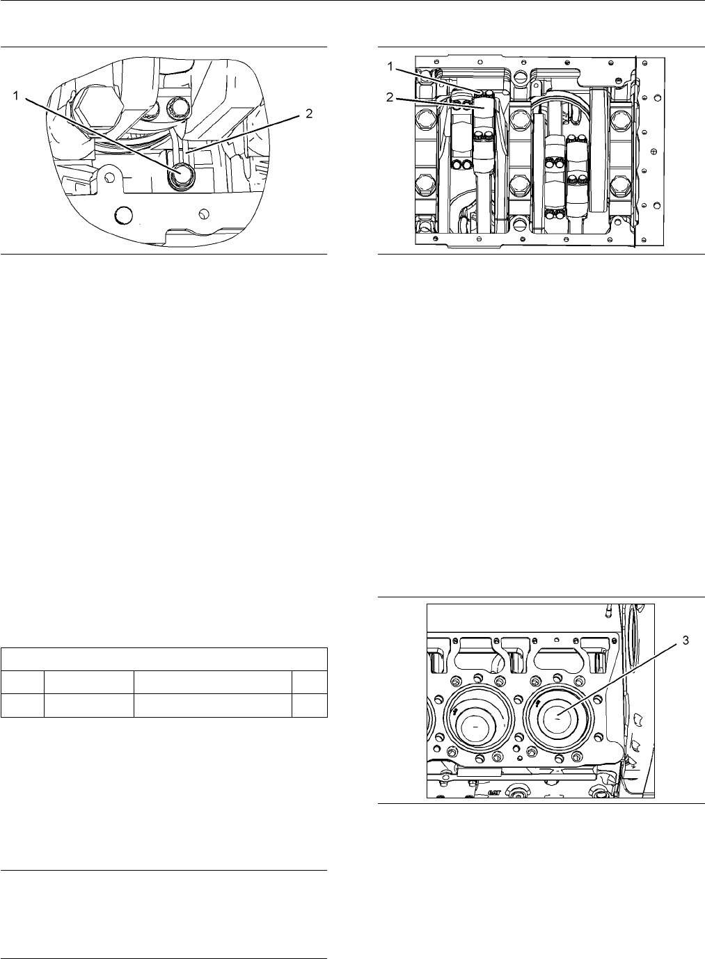
1. Use Tooling (A) to rotate the crankshaft in order to
gain access to the piston cooling jet.
2. Position piston cooling jet (2) in the cylinder block.
Install bolt (1). Tighten the bolt to a torque of
25±6N·m(18±4lbft).
End By:
a. Install the engine oil pump. Refer to Disassembly
and Assembly, “Engine Oil Pump - Install”.
i02295112
Pistons and Connecting Rods
-Remove
SMCS Code: 1225-011
Removal Procedure
Table 60
Required Tools
Tool Part Number Part Description Qty
A 9S-9082 Engine Turning Tool 1
Start By:
a. Remove the cylinder head. Refer to Disassembly
and Assembly, “Cylinder Head - Remove”.
b. Remove the piston cooling jets. Refer to
Disassembly and Assembly, “Piston Cooling Jets
- Remove and Install”.
NOTICE
Keep all parts clean from contaminants.
Contaminants may cause rapid wear and shortened
component life.
g01149594
Illustration 243
1. Use Tooling (A) to rotate the crankshaft until the
piston is at the bottom center.
2. Remove the carbon ridge from the top inside
surface of the cylinder liner.
3. Inspect the connecting rod and connecting rod cap
for the proper identification mark. The connecting
rod and the connecting rod cap should have an
etched number on the side. The number should
match the cylinder number. Mark the connecting
rod and the connecting rod cap, if necessary.
Note: Do not stamp the connecting rod assembly.
Stamping or punching the connecting rod assembly
could cause the connecting rod to fracture.
4. Remove bolts (1) and connecting rod bearing cap
(2).
g011495
95
Illustration 244
5. Remove piston (3) and the connecting rod from
the cylinder liner .
Contents Summary of C27 and C32 Generator Sets Engines Disassembly and Assembly
- Page 1RENR9716-02 September 2008 Disassembly and Assembly C27 and C32 Generator Sets Engines DWB1-Up (Generator Set) SXC1-Up (Generator Set) MED1-Up (Power Module) WDR1-Up (Generator Set) SAFETY.CAT.COM
- Page 2i01658146 Important Safety Information Most accidents that involve product operation, maintenance and repair are caused by failure to observe basic safety rules or precautions. An accident can often be avoided by recognizing potentially hazardous situations before an accident occurs. A person must b
- Page 3RENR9716-02 3 Table of Contents Table of Contents Vibration Damper and Pulley - Remove and Install ............................................................................. 53 Crankshaft Front Seal - Remove .......................... 54 Crankshaft Front Seal - Install ...........................
- Page 44 RENR9716-02 Disassembly and Assembly Section Disassembly and Assembly Section i02747487 Engine - Remove SMCS Code: 1000-011 Removal Procedure Table 1 Required Tools g01291160 Illustration 2 Part Tool Number Part Description Qty 2. Disconnect harness assembly (6). A 138-7573 Link Bracket 2 B 238-95
- Page 5RENR9716-02 5 Disassembly and Assembly Section 7. Disconnect clamp (15). g01291225 Illustration 8 8. Remove bolts (16). Remove guard (17). g01291179 Illustration 5 5. Remove bolts (11). Remove bolts (12). Repeat for the opposite side. Disconnect tube assembly (13). Repeat for the opposite side. g012
- Page 66 RENR9716-02 Disassembly and Assembly Section g01291232 g01291246 Illustration 11 Illustration 14 13. Attach Tooling (D) onto engine (24). Attach Tooling (E) and a suitable lifting device onto Tooling (D). The weight of engine (24) is approximately 3527 kg (7775 lb). g01291243 Illustration 12 11. I
- Page 7RENR9716-02 7 Disassembly and Assembly Section g01291246 g01291232 Illustration 16 Illustration 19 1. Attach Tooling (D) onto engine (24). Attach Tooling 3. Install bolts (21). Use Tooling (B) in order to rotate (E) and a suitable lifting device onto Tooling the engine. Install bolts (22). (D). The
- Page 88 RENR9716-02 Disassembly and Assembly Section g01291227 g01291183 Illustration 22 Illustration 25 6. Install guard (19). Install bolts (18). 9. Attach Tooling (A) and a suitable lifting device onto exhaust elbow (14). The weight of exhaust elbow (14) is approximately 34 kg (75 lb). Install exhaust
- Page 9RENR9716-02 9 Disassembly and Assembly Section 11. Connect clamp (10). End By: a. Install the cooling package. Refer to Disassembly and Assembly, “Cooling System Package (Radiator, Aftercooler, Fuel Cooler) - Install”. i02580978 Fuel Priming Pump - Remove and Install SMCS Code: 1258-010 Removal Proc
- Page 1010 RENR9716-02 Disassembly and Assembly Section Installation Procedure 1. Turn the fuel supply to the OFF position. g01292755 Illustration 32 1. Position the gasket and fuel priming pump (2) on the fuel filter base. 2. Install bolts (1). g01292764 Illustration 33 i02580993 2. Use Tooling (A) to remo
- Page 11RENR9716-02 11 Disassembly and Assembly Section NOTICE Care must be taken to ensure that fluids are contained during performance of inspection, maintenance, test- ing, adjusting and repair of the product. Be prepared to collect the fluid with suitable containers before open- ing any compartment or d
- Page 1212 RENR9716-02 Disassembly and Assembly Section g01292832 Illustration 36 1. Position base assembly (4) on the cylinder block and install bolts (1). 2. Connect hose assemblies (2) and (3). g01143748 Illustration 37 3. Install a new fuel filter and water separator (5) on base assembly (4). 2. Disconn
- Page 13RENR9716-02 13 Disassembly and Assembly Section g01114892 Illustration 39 1. Disconnect harness assembly (1). 2. Remove bridge assemblies (3). Illustration 38 g01143748 NOTICE If the injector hold down bolt is loose during the re- 1. Install the O-ring seal on fuel transfer pump (1). moval procedure
- Page 1414 RENR9716-02 Disassembly and Assembly Section i03143340 Electronic Unit Injector - Install SMCS Code: 1290-012 Installation Procedure Table 6 Required Tools Tool Part Number Part Description Qty B 8T-2998 Lubricant 1 1U-5718 Vacuum Pump 1 g01114892 Illustration 41 169-7372 Fluid Sampling Bottle 1
- Page 15RENR9716-02 15 Disassembly and Assembly Section NOTICE NOTICE When an electronic unit injector is replaced, the new Keep all parts clean from contaminants. electronic injector code must be programmed into the engine’s personality module software by using the cal- Contaminants may cause rapid wear an
- Page 1616 RENR9716-02 Disassembly and Assembly Section i02287628 Note: Do not apply Tooling (C) to the cylinder head surfaces. Apply Tooling (C) on the electronic unit Electronic Unit Injector Sleeve injector sleeve only. - Install 4. Lubricate O-ring seals (2) with clean engine oil. SMCS Code: 1713-012 In
- Page 17RENR9716-02 17 Disassembly and Assembly Section i02287744 Turbocharger - Remove SMCS Code: 1052-011 Removal Procedure NOTICE Care must be taken to ensure that fluids are contained during performance of inspection, maintenance, test- ing, adjusting and repair of the product. Be prepared to collect th
- Page 1818 RENR9716-02 Disassembly and Assembly Section 1. Position compressor housing (1) and turbine housing (5) on turbocharger cartridge (3). Note: Ensure that the mating surfaces are flush. 2. Tighten the nuts on V-band clamp (2) to a torque of 14 ± 1 N·m (10 ± 1 lb ft). Use a soft hammer to lightly hi
- Page 19RENR9716-02 19 Disassembly and Assembly Section g01145002 g01218139 Illustration 52 Illustration 53 1. Position the gasket on the exhaust manifold. 2. Remove locknuts (6) from exhaust manifold (7). 2. Apply Tooling (A) to the threads of the exhaust 3. Remove spacers (2) and (3) from exhaust manifold
- Page 2020 RENR9716-02 Disassembly and Assembly Section i02300073 Inlet and Exhaust Valve Springs - Remove and Install SMCS Code: 1108-010 Removal Procedure Table 11 Required Tools Tool Part Number Part Description Qty g00566145 A 9U-7241 Valve Spring Compressor 1 Illustration 55 B 8S-2263 Spring Tester 1 1
- Page 21RENR9716-02 21 Disassembly and Assembly Section NOTICE Keep all parts clean from contaminants. Contaminants may cause rapid wear and shortened component life. 1. Lubricate the valve stems with clean engine oil. g01043625 Illustration 57 Personal injury can result from being struck by parts propelled
- Page 2222 RENR9716-02 Disassembly and Assembly Section End By: a. Install the electronic unit injectors. Refer to Disassembly and Assembly, “Electronic Unit Injector - Install”. i02642655 Inlet and Exhaust Valves - Remove and Install SMCS Code: 1105-010 Removal Procedure Table 13 Required Tools Tool Part N
- Page 23RENR9716-02 23 Disassembly and Assembly Section Installation Procedure 3. Install inner valve spring (4) and outer valve spring (5) on valve (1). Table 14 Required Tools 4. Install valve rotator (3) on valve (1). Tool Part Number Part Description Qty 5. Use Tooling (A) to compress inner valve spring
- Page 2424 RENR9716-02 Disassembly and Assembly Section Note: Tooling (B) must be used in order to install the valve guide to the correct height. Height to top of valve guide from cylinder head surface ..... 35.00 ± 0.50 mm (1.378 ± 0.020 inch) Note: For more information, refer to Specifications, “Cylinder
- Page 25RENR9716-02 25 Disassembly and Assembly Section 1. Use Tooling (A) to remove valve seat insert (1) i02438648 from the cylinder head. Engine Oil Filter Base - 2. Clean the bores in the cylinder head for the valve Remove seat inserts. Remove any rough areas from the bores. SMCS Code: 1306-011 Installa
- Page 2626 RENR9716-02 Disassembly and Assembly Section 2. Use Tooling (A) in order to remove engine oil 3. Remove springs (3) and plungers (2) from oil filter filters (6). base assembly (1). 3. Remove bolts (1), (2), (4), and (5). i02127824 4. Remove engine oil filter base (3). Engine Oil Filter Base - Ass
- Page 27RENR9716-02 27 Disassembly and Assembly Section End By: i02438849 a. Install the engine oil filter base. Refer to Engine Oil Cooler - Remove Disassembly and Assembly, “Engine Oil Filter Base - Install”. SMCS Code: 1378-011 i02438813 Removal Procedure Engine Oil Filter Base - Install Start By: SMCS C
- Page 2828 RENR9716-02 Disassembly and Assembly Section 4. Remove engine oil cooler (3). i02439263 5. Remove the O-ring seals from engine oil cooler Engine Oil Pump - Remove (3). SMCS Code: 1304-011 i02438914 Removal Procedure Engine Oil Cooler - Install Start By: SMCS Code: 1378-012 a. Remove the engine oi
- Page 29RENR9716-02 29 Disassembly and Assembly Section i02439652 3. Remove bolts (4) and separate cover assembly (3) from body assembly (1). Engine Oil Pump - Disassemble 4. Use Tooling (A) and a suitable press in order to SMCS Code: 1304-015 remove the bearings from cover assembly (3). Disassembly Procedu
- Page 3030 RENR9716-02 Disassembly and Assembly Section 5. Use Tooling (A) to install the bearings in cover assembly (3) until the bearings are even with the outside surface of cover assembly (3). Install the bearings so the junctions in the bearings are Angle (Y). Angle (Y) is 30 ± 15 degrees from the cent
- Page 31RENR9716-02 31 Disassembly and Assembly Section i02440626 Water Pump - Remove SMCS Code: 1361-011 Removal Procedure NOTICE Care must be taken to ensure that fluids are contained during performance of inspection, maintenance, test- ing, adjusting and repair of the product. Be prepared to collect the
- Page 3232 RENR9716-02 Disassembly and Assembly Section Note: The water pump seal can be replaced without i02394663 removing the water pump from the engine. Water Pump - Assemble Note: An intermittent leakage of a small amount of coolant from the hole in the water pump housing is SMCS Code: 1361-016 not an
- Page 33RENR9716-02 33 Disassembly and Assembly Section 7. Use Tooling (C) to install seal assembly (12) onto shaft (10) until the stationary cup is fully seated into housing (3). 8. Install impeller (5) on shaft (10). Install washer (8) and bolt (9). Tighten bolt (9) to a torque of 39 ± 3 N·m (29 ± 2 lb ft
- Page 3434 RENR9716-02 Disassembly and Assembly Section g01219336 g01223744 Illustration 83 Illustration 85 2. Disconnect hose assembly (1) and elbow (3). 2. Install water temperature regulators (7) and O-ring seals (6) in water temperature regulator housing 3. Remove bolts (2) and bolts (4). Remove water (
- Page 35RENR9716-02 35 Disassembly and Assembly Section i02576096 Cooling System Package (Radiator, Aftercooler, Fuel Cooler) - Remove SMCS Code: 1063-011; 1353-011; 1712-011 Removal Procedure Table 26 Required Tools Part Tool Part Description Qty Illustration 88 g01290915 Number A 189-0410 Shackle As 2 3.
- Page 3636 RENR9716-02 Disassembly and Assembly Section g01290930 g01290940 Illustration 91 Illustration 94 6. Disconnect bottom radiator hose (5). Disconnect 9. Attach Tooling (A) and a suitable lifting device bottom aftercooler tube (6). onto cooling package (10). The weight of cooling package (10) is app
- Page 37RENR9716-02 37 Disassembly and Assembly Section NOTICE Care must be taken to ensure that fluids are contained during performance of inspection, maintenance, test- ing, adjusting and repair of the product. Be prepared to collect the fluid with suitable containers before open- ing any compartment or d
- Page 3838 RENR9716-02 Disassembly and Assembly Section g01290917 g01290908 Illustration 101 Illustration 104 6. Connect top aftercooler tube (4). 9. Install clamp (1). Repeat for the opposite side. 10. Fill the cooling system with coolant. Refer to Operation and Maintenance Manual, “Cooling System Coolant
- Page 39RENR9716-02 39 Disassembly and Assembly Section NOTICE Care must be taken to ensure that fluids are contained during performance of inspection, maintenance, test- ing, adjusting and repair of the product. Be prepared to collect the fluid with suitable containers before open- ing any compartment or d
- Page 4040 RENR9716-02 Disassembly and Assembly Section g01290934 g01294232 Illustration 110 Illustration 113 7. Disconnect hose assembly (8) from fuel cooler (7). 10. Attach Tooling (A) and a suitable lifting device onto aftercooler (12). The weight of aftercooler (12) is approximately 227 kg (500 lb). g01
- Page 41RENR9716-02 41 Disassembly and Assembly Section g01294232 g01290939 Illustration 115 Illustration 118 1. Attach Tooling (A) and a suitable lifting device onto 5. Connect hose assembly (9) onto fuel cooler (7). aftercooler (12). The weight of aftercooler (12) is approximately 227 kg (500 lb). Install
- Page 4242 RENR9716-02 Disassembly and Assembly Section g01290917 g01290908 Illustration 121 Illustration 124 8. Connect top aftercooler tube (4). 11. Install clamp (1). Repeat for the opposite side. 12. Fill the cooling system with coolant. Refer to Operation and Maintenance Manual, “Cooling System Coolant
- Page 43RENR9716-02 43 Disassembly and Assembly Section NOTICE Care must be taken to ensure that fluids are contained during performance of inspection, maintenance, test- ing, adjusting and repair of the product. Be prepared to collect the fluid with suitable containers before open- ing any compartment or d
- Page 4444 RENR9716-02 Disassembly and Assembly Section g01292912 Illustration 132 1. Attach Tooling (A) and a suitable lifting device onto radiator top tank (2). The weight of the radiator is approximately 227 kg (500 lb). g01294580 Illustration 130 6. Remove bolts (7). Remove bolts (8). Remove support (9)
- Page 45RENR9716-02 45 Disassembly and Assembly Section g01292911 Illustration 138 8. Install the upper and the lower radiator guards (1). End By: g01294579 a. Install the aftercooler. Refer to Disassembly and Illustration 135 Assembly, “Aftercooler - Install”. 4. Install bolts (6). i02444868 Engine Support
- Page 4646 RENR9716-02 Disassembly and Assembly Section Installation Procedure (Type 1) Installation Procedure (Type 2) g01221659 g01221663 Illustration 140 Illustration 142 1. Position engine support (2) on the engine. 1. Use a suitable lifting device to position engine support (4) on the engine. The weigh
- Page 47RENR9716-02 47 Disassembly and Assembly Section 4. Use Tooling (A) and a suitable press to remove NOTICE the bearing from gear assembly (6). Care must be taken to ensure that fluids are contained during performance of inspection, maintenance, test- 5. Remove bolts (2), gear assembly (1), and shaft i
- Page 4848 RENR9716-02 Disassembly and Assembly Section i02442469 Gear Group (Rear) - Install SMCS Code: 1206-012; 1212-012 Installation Procedure Table 33 Required Tools Part Tool Number Part Description Qty A 1P-0510 Driver Group 1 NOTICE Keep all parts clean from contaminants. Contaminants may cause rapi
- Page 49RENR9716-02 49 Disassembly and Assembly Section 8. Install shaft assembly (3), gear assembly (1), and bolts (2). 9. Use Tooling (A) and a suitable press to install the bearing in gear assembly (6). Install the bearing to a depth of 2.6 ± 0.5 mm (0.10 ± 0.02 inch). 10. Install shaft assembly (7), gea
- Page 5050 RENR9716-02 Disassembly and Assembly Section NOTICE Keep all parts clean from contaminants. Contaminants may cause rapid wear and shortened component life. g01220437 Illustration 151 Note: Ring gear (3) must be installed with the chamfered side of the teeth upward. The chamfered side of the gear
- Page 51RENR9716-02 51 Disassembly and Assembly Section b. Remove the electric starting motor. Refer to NOTICE Disassembly and Assembly, “Electric Starting Keep all parts clean from contaminants. Motor - Remove and Install”. Contaminants may cause rapid wear and shortened NOTICE component life. Keep all par
- Page 5252 RENR9716-02 Disassembly and Assembly Section Installation Procedure Table 39 Required Tools Part Tool Number Part Description Qty A 138-7574 Link Bracket 2 - Guide Stud B 2 1/2 - 13 NC by 7 inch NOTICE Keep all parts clean from contaminants. Contaminants may cause rapid wear and shortened compone
- Page 53RENR9716-02 53 Disassembly and Assembly Section End By: a. Install the electric starting motor. Refer to Disassembly and Assembly, “Electric Starting Motor - Remove and Install”. b. Install the crankshaft rear seal. Refer to Disassembly and Assembly, “Crankshaft Rear Seal - Install”. i02443805 Vibra
- Page 5454 RENR9716-02 Disassembly and Assembly Section NOTICE Keep all parts clean from contaminants. Contaminants may cause rapid wear and shortened component life. g01221066 g01221272 Illustration 160 Illustration 161 1. Install Tooling (A) in the adapter. 1. Remove bolts (1) and adapter (2). 2. Attach a
- Page 55RENR9716-02 55 Disassembly and Assembly Section i02444556 Crankshaft Front Seal - Install SMCS Code: 1160-012 Installation Procedure Table 43 Required Tools Part Tool Number Part Description Qty 5P-1733 Seal Locator 1 g01221272 5P-1737 Bolt 3 Illustration 164 B 9S-8858 Nut (Seal Installer) 1 3. Inst
- Page 5656 RENR9716-02 Disassembly and Assembly Section g01147620 Illustration 167 1. Apply clean engine oil to shaft (7), the bearing bore, and the thrust faces prior to installation. Install shaft (7) and bolts (6). Tighten bolts (6) to a torque of 55 ± 10 N·m (41 ± 7 lb ft). g01147593 Illustration 165 1.
- Page 57RENR9716-02 57 Disassembly and Assembly Section i02445219 Housing (Front) - Remove SMCS Code: 1151-011 Removal Procedure Start By: a. Remove the water temperature regulator housing. Refer to Disassembly and Assembly, “Water Temperature Regulator Housing - Remove and Install”. b. Remove the water pum
- Page 5858 RENR9716-02 Disassembly and Assembly Section i02445708 Housing (Front) - Install SMCS Code: 1151-012 Installation Procedure Table 44 Required Tools Part Tool Number Part Description Qty A 4C-9612 Silicone Sealant 1 g01221953 Illustration 171 NOTICE 5. Disconnect bracket (7) and elbows (8). Keep a
- Page 59RENR9716-02 59 Disassembly and Assembly Section g01221953 Illustration 174 6. Connect elbows (8) and bracket (7). g01221893 Illustration 177 9. Install alternator bracket (3) on front housing (4). 10. Install covers (1). 11. Connect hose assemblies (2) to front housing (4). End By: a. Install the ca
- Page 6060 RENR9716-02 Disassembly and Assembly Section i02290579 Housing (Rear) - Remove SMCS Code: 1157-011 Removal Procedure Start By: a. Remove the rear gear group. Refer to Disassembly and Assembly, “Gear Group (Rear) - Remove”. NOTICE Keep all parts clean from contaminants. Contaminants may cause rapi
- Page 61RENR9716-02 61 Disassembly and Assembly Section NOTICE Keep all parts clean from contaminants. Contaminants may cause rapid wear and shortened component life. 1. Apply Tooling (A) to the bottom of the rear housing at the junction of the cylinder block and the engine oil pan. g01147149 Illustration 1
- Page 6262 RENR9716-02 Disassembly and Assembly Section g01147941 Illustration 183 1. Remove bolts (1) and valve mechanism covers (2). Installation Procedure g01147132 Illustration 182 NOTICE 6. Install bolts (2). Keep all parts clean from contaminants. 7. Connect hose assembly (1). Contaminants may cause r
- Page 63RENR9716-02 63 Disassembly and Assembly Section NOTICE Keep all parts clean from contaminants. Contaminants may cause rapid wear and shortened component life. g01147965 Illustration 186 1. Install the seal on valve mechanism cover base (3). 2. Position valve mechanism cover base (3) on the cylinder
- Page 6464 RENR9716-02 Disassembly and Assembly Section Start By: a. Remove the valve mechanism cover. Refer to Disassembly and Assembly, “Valve Mechanism Cover - Remove and Install”. NOTICE Keep all parts clean from contaminants. Contaminants may cause rapid wear and shortened component life. g01047557 Ill
- Page 65RENR9716-02 65 Disassembly and Assembly Section i03203773 Rocker Arm and Shaft - Install SMCS Code: 1102-012 Installation Procedure Table 47 Required Tools Part Tool Number Part Description Qty A 124-2946 Lifting Bracket 1 g01047557 Illustration 189 NOTICE Note: Do not reuse the O-ring seal on the a
- Page 6666 RENR9716-02 Disassembly and Assembly Section 1. Position rocker arm shaft assembly (4), valve rocker arms (3), and electronic unit injector rocker NOTICE arms (1) as a unit with Tooling (A) on the cylinder Care must be taken to ensure that fluids are contained head. during performance of inspecti
- Page 67RENR9716-02 67 Disassembly and Assembly Section g01222230 g01148246 Illustration 193 Illustration 196 3. Remove bolts (2) and gear (3). 6. Remove elbow (8). Disconnect hose assembly (9). g01222233 Illustration 194 4. Remove bolts (4), thrust plate (5), and adapter assembly (6). g01148489 Illustratio
- Page 6868 RENR9716-02 Disassembly and Assembly Section 10. Remove bolts (15) and damper (16). 15. Attach Tooling (A) and a suitable lifting device to cylinder head (25). Attach Tooling (B) to the side of cylinder head (25) that is near the turbocharger. The weight of cylinder head (25) is approximately 365
- Page 69RENR9716-02 69 Disassembly and Assembly Section g01148791 Illustration 203 1. Install the gaskets, O-ring seals, and the spacer plate on the engine. 2. Attach Tooling (A) and a suitable lifting device to cylinder head (25). Attach Tooling (B) to the side of cylinder head (25) that is near the turboc
- Page 7070 RENR9716-02 Disassembly and Assembly Section 8. Install adapter assembly (19) and sealing plate 11. Install bracket (14). (18). Install bolts (17). 12. Connect harness assembly (13) and harness assembly (12). 13. Install cover (10) and elbow (11). g01148492 Illustration 206 g01148246 Illustration
- Page 71RENR9716-02 71 Disassembly and Assembly Section End By: a. Install the fuel transfer pump. Refer to Disassembly and Assembly, “Fuel Transfer Pump - Install”. b. Install the valve mechanism cover base. Refer to Disassembly and Assembly, “Valve Mechanism Cover Base - Remove and Install”. c. Install th
- Page 7272 RENR9716-02 Disassembly and Assembly Section 1. Drain the coolant from the cooling system into a suitable container for storage or disposal. Refer to Operation and Maintenance Manual, “Cooling System Coolant - Change”. g01222234 Illustration 218 5. Use bolt (4) in order to remove sealing plate (7
- Page 73RENR9716-02 73 Disassembly and Assembly Section Note: Rotate the camshaft during removal. This will prevent the camshaft from binding in the camshaft bearings. i02446568 Camshaft - Install SMCS Code: 1210-012 Installation Procedure Table 51 g01160261 Required Tools Illustration 221 Part 8. Remove bo
- Page 7474 RENR9716-02 Disassembly and Assembly Section g01160265 g01160259 Illustration 223 Illustration 225 2. Install Tooling (A) and Tooling (B) on the rear of camshaft (15). Install Tooling (A) on the front of camshaft (15). 3. Install Tooling (C) on the front housing or the rear housing. Tooling (C) i
- Page 75RENR9716-02 75 Disassembly and Assembly Section g01222314 g01151468 Illustration 228 Illustration 231 10. Install new O-ring seals and sealing plate (7). 12. Install gear (3) and bolts (2). 13. Tighten the bolts to a torque of 240 ± 40 N·m (177 ± 30 lb ft). Tighten the bolts in the following sequenc
- Page 7676 RENR9716-02 Disassembly and Assembly Section i02451045 Note: Tooling (C) is installed on the outside of the cylinder head. Tooling (C) is required in order to Camshaft Bearings - Remove remove all the camshaft bearings from the cylinder head. SMCS Code: 1211-011 4. Use Tooling (A) to remove camsh
- Page 77RENR9716-02 77 Disassembly and Assembly Section 1. Install the No. 7 camshaft bearing (rear), as Note: When the chamfer of Tooling (E) contacts the follows: face of the camshaft bore, the camshaft bearing is properly installed. a. Insert the large end of Tooling (B) into the No. 7 camshaft bore. b.
- Page 7878 RENR9716-02 Disassembly and Assembly Section i02447352 2. Remove tube assemblies (1) from engine oil pan (3). Engine Oil Pan - Remove and Install 3. Use Tooling (A) to support engine oil pan (3). The weight of engine oil pan (3) is approximately 25 kg SMCS Code: 1302-010 (55 lb). 4. Remove bolts
- Page 79RENR9716-02 79 Disassembly and Assembly Section i02294951 Cylinder Liner - Remove SMCS Code: 1216-011 Removal Procedure Table 56 Required Tools Tool Part Number Part Description Qty A 5P-8665(1) Cylinder Liner Puller Gp 1 (1) The 6V-9448 Cylinder Pack Puller is an optional Tool for removing the cyli
- Page 8080 RENR9716-02 Disassembly and Assembly Section Start By: a. Remove the engine oil pump. Refer to Disassembly and Assembly, “Engine Oil Pump - Remove”. NOTICE Keep all parts clean from contaminants. Contaminants may cause rapid wear and shortened component life. g01149469 Illustration 240 2. Install
- Page 81RENR9716-02 81 Disassembly and Assembly Section g01149484 g01149594 Illustration 242 Illustration 243 1. Use Tooling (A) to rotate the crankshaft in order to 1. Use Tooling (A) to rotate the crankshaft until the gain access to the piston cooling jet. piston is at the bottom center. 2. Position pisto
- Page 8282 RENR9716-02 Disassembly and Assembly Section i02447789 2. Remove upper connecting rod bearing (8) from connecting rod (6). Pistons and Connecting Rods - Disassemble 3. Use Tooling (A) to remove pin retainers (5) from piston body assembly (4). SMCS Code: 1225-015 4. Remove connecting rod pin (7) a
- Page 83RENR9716-02 83 Disassembly and Assembly Section Note: Ensure that the bearing locking tab is located in the notch of the connecting rod bearing cap. 10. Ensure that the dowels are installed in the connecting rod bearing cap. End By: a. Install the pistons and connecting rods. Refer to Disassembly an
- Page 8484 RENR9716-02 Disassembly and Assembly Section Note: Ensure that the number on the side of the connecting rod bearing cap is on the same side as the number on the connecting rod. The bearing tabs of the connecting rod bearing cap and the connecting rod are located on the side opposite of the piston
- Page 85RENR9716-02 85 Disassembly and Assembly Section Start By: i02295910 a. Remove the engine oil pump. Refer to Connecting Rod Bearings - Disassembly and Assembly, “Engine Oil Pump Install - Remove”. SMCS Code: 1219-012 NOTICE Keep all parts clean from contaminants. Installation Procedure Contaminants m
- Page 8686 RENR9716-02 Disassembly and Assembly Section 4. Pull the connecting rod onto the crankshaft. i02296017 Crankshaft Main Bearings - Remove SMCS Code: 1203-011 Removal Procedure Table 66 Required Tools Part Tool Number Part Description Qty A 2P-5518 Bearing Tool 1 g01149651 Illustration 251 Start By
- Page 87RENR9716-02 87 Disassembly and Assembly Section Note: Install the main bearings dry when clearance checks are performed. Refer to Disassembly and Assembly, “Bearing Clearance - Check”. Apply clean engine oil on the main bearings for final assembly. Note: Ensure that the main bearings are installed s
- Page 8888 RENR9716-02 Disassembly and Assembly Section Note: Bolt (C) is on the bearing tab side of the main bearing cap. g. Rotate the crankshaft in order to ensure that the crankshaft turns freely. 7. Use Tooling (B) to check the crankshaft end play. Ensure that Tooling (B) is against a machined surface.
- Page 89RENR9716-02 89 Disassembly and Assembly Section c. Remove the piston cooling jets. Refer to 6. Remove crankshaft (6) from the cylinder block. Disassembly and Assembly, “Piston Cooling Jets - Remove and Install”. 7. Remove the thrust plates from each side of the No. 4 main bearing. NOTICE Keep all pa
- Page 9090 RENR9716-02 Disassembly and Assembly Section i02296800 Note: Ensure that the main bearings are installed so that the bearing tabs fit into the notch in the cylinder Crankshaft - Install block. The upper halves of the main bearings have the oil groove and the oil hole. SMCS Code: 1202-012 Installa
- Page 91RENR9716-02 91 Disassembly and Assembly Section Note: Bolt (B) is on the opposite side of the bearing Note: Ensure that the number on the side of the tab of the main bearing cap. connecting rod bearing cap is on the same side as the number on the connecting rod. The bearing tabs c. Tighten Bolt (B)
- Page 9292 RENR9716-02 Disassembly and Assembly Section i02717761 The technician must be very careful to use Tooling (A) correctly. The following points must be remembered: Bearing Clearance - Check • Ensure that the backs of the bearings and the SMCS Code: 1203-535; 1219-535 bores are clean and dry. Measur
- Page 93RENR9716-02 93 Disassembly and Assembly Section Note: When Tooling (A) is used, the readings can sometimes be unclear. For example, all parts of Tooling (A) are not the same width. Measure the major width in order to ensure that the parts are within the specification range. Refer to Specifications M
- Page 9494 RENR9716-02 Disassembly and Assembly Section i02297803 Crankshaft Position Sensor - Remove and Install SMCS Code: 1912-010 Removal Procedure NOTICE Care must be taken to ensure that fluids are contained during performance of inspection, maintenance, test- ing, adjusting and repair of the product.
- Page 95RENR9716-02 95 Disassembly and Assembly Section Installation Procedure NOTICE NOTICE Keep all parts clean from contaminants. Keep all parts clean from contaminants. Contaminants may cause rapid wear and shortened Contaminants may cause rapid wear and shortened component life. component life. 1. Drai
- Page 9696 RENR9716-02 Disassembly and Assembly Section 1. Install a new O-ring seal on coolant temperature 2. Remove engine oil pressure sensor (1) from the sensor (2). adapter on the cylinder block. 2. Install coolant temperature sensor (2) and tighten 3. Remove the O-ring seal from engine oil pressure to
- Page 97RENR9716-02 97 Disassembly and Assembly Section i02581037 Installation Procedure Fuel Pressure Sensor - NOTICE Remove and Install Keep all parts clean from contaminants. SMCS Code: 7414-010 Contaminants may cause rapid wear and shortened component life. Removal Procedure NOTICE Care must be taken to
- Page 9898 RENR9716-02 Disassembly and Assembly Section 2. Install fuel temperature sensor (2). Tighten fuel NOTICE temperature sensor (2) to a torque of 20 ± 5 N·m Keep all parts clean from contaminants. (15 ± 4 lb ft). Contaminants may cause rapid wear and shortened 3. Connect harness assembly (1). compon
- Page 99RENR9716-02 99 Disassembly and Assembly Section 3. Remove the O-ring seal from inlet air temperature sensor (2). Installation Procedure NOTICE Keep all parts clean from contaminants. Contaminants may cause rapid wear and shortened component life. g01223056 Illustration 279 1. Install a new O-ring se
- Page 100100 RENR9716-02 Disassembly and Assembly Section 1. Remove bolts (1). Repeat for the opposite side. i02755046 Remove bottom belt guard (2). Fan Guard - Remove and Install SMCS Code: 1360-010 Removal Procedure g01289709 Illustration 283 2. Remove bolt (3). Repeat for the opposite side. Remove upper b
- Page 101RENR9716-02 101 Disassembly and Assembly Section g01289778 Illustration 289 2. Install lower fan guard (2). Install bolts (1). i02755088 Fan - Remove and Install Illustration 291 g01289733 SMCS Code: 1356-010 2. Remove bolts (2). Remove fan (1). Removal Procedure Installation Procedure Table 71 Tabl
- Page 102102 RENR9716-02 Disassembly and Assembly Section g01289730 Illustration 293 2. Remove Tooling (A) and the suitable lifting device from fan (1). End By: g01289585 Illustration 294 a. Install the fan guard. Refer to Disassembly and Assembly, “Fan Guard - Remove and Install”. 2. Loosen bolts (1). Loose
- Page 103RENR9716-02 103 Disassembly and Assembly Section Installation Procedure b. Install the fan. Refer to Disassembly and Assembly, “Fan - Remove and Install”. i02417465 Electronic Control Module - Remove and Install SMCS Code: 1901-010 Removal Procedure 1. Turn the battery disconnect switch to the “OFF”
- Page 104104 RENR9716-02 Disassembly and Assembly Section Installation Procedure g01223195 Illustration 300 2. Remove V-belt (1) from alternator (3). 3. Disconnect the harness assemblies from alternator (3). g01208278 4. Remove bolt (2) and bolt (4). Illustration 299 5. Remove alternator (3) from the mountin
- Page 105RENR9716-02 105 Disassembly and Assembly Section i02419387 Installation Procedure Electric Starting Motor - Remove and Install SMCS Code: 1453-010 Removal Procedure Personal injury can result from failure to discon- nect the battery. First, disconnect the negative battery cable. Then, disconnect the
- Page 106106 RENR9716-02 Index Section Index A Crankshaft Main Bearings - Install......................... 87 Installation Procedure ........................................ 87 Aftercooler - Install................................................. 40 Crankshaft Main Bearings - Remove..................... 86
- Page 107RENR9716-02 107 Index Section Engine Oil Pan - Remove and Install..................... 78 G Installation Procedure ........................................ 78 Removal Procedure ........................................... 78 Gear Group (Front) - Install ................................... 56 Engine O
- Page 108R Water Temperature Regulator Housing - Remove and Install ................................................................... 33 Radiator Core - Install............................................ 44 Installation Procedure ........................................ 34 Installation Procedure .........