416C, 426C, 428C, 436C and 438C Backhoe Loaders Operation and Maintenance Manual Page 28
Operation and Maintenance Manual
213
Maintenance Section
Fuel System - Prime
2. Remove the oil fill/drain plug in order to check
the oil level.
3. The oil should be level with the bottom of the
plug threads.
4. Clean the plug and install the plug.
5. Repeat the procedure for the other final drive.
i00609513
Fuel System - Prime
SMCS Code: 1258
Air can enter the system under the following
conditions.
•
The fuel tank is drained during normal operation.
•
The low pressure fuel lines are disconnected.
•
A part of the low pressure fuel system leaks
during engine operation.
If air enters the fuel system, the air must be
eliminated from the system before the engine can
be started.
If the engine has been stopped by air in the fuel
system, perform the following procedures:
•
Make sure that fuel has been added to the tank.
•
Make sure that the leakage problem has been
corrected.
•
Make sure that the electrical stop control is
connected.
•
Operate the starter motor until the engine starts.
1. Make sure the electrical stop control is
connected. Turn the engine start switch key to
the ON position.
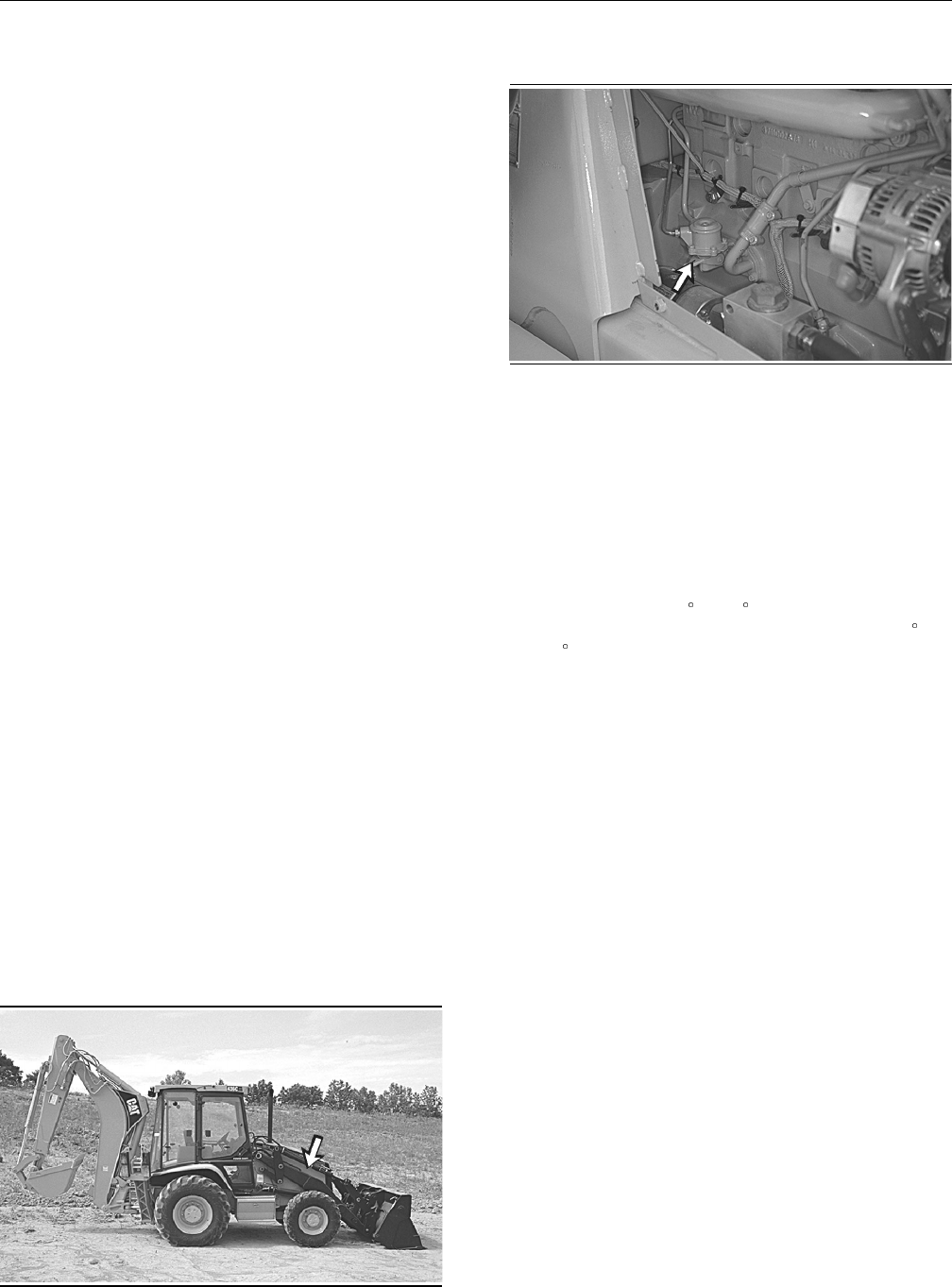
g00291785
Illustration 338
2. Remove the access panel on the right side of
the machine.
g00291786
Illustration 339
3. Operate the lever of the fuel lift pump slowly
for approximately two minutes. If the drive cam
of the fuel lift pump is at the point of maximum
cam lift, the priming lever will not operate. In
this situation, the crankshaft must be turned one
revolution.
4. Operate the starter motor until the engine starts.
Refer to Operation and Maintenance Manual,
“Starting Above 0
C (32 F)” and Operation
and Maintenance Manual, “Starting Below 0
C
(32
F)”.
5. Check for air in the fuel system if the engine runs
roughly after the engine runs correctly for a short
period of time. Check for air in the fuel system if
the engine stops after the engine runs correctly
for a short period of time. If there is air in the fuel
system, check the low pressure fuel system for
a leak. Correct the problem and repeat Step3
through Step4.
i00609515
Fuel System Filter - Replace
SMCS Code: 1261
1. Empty the bucket. Remove the pin that secures
the loader lift arm brace to the left loader lift arm.
Raise the loader arm to the maximum height.
2. Position the loader lift arm brace over the left lift
cylinder rod with the flat end against the cylinder
end.
3. Push the pin through the holes of the loader lift
arm brace and install the cotter pin.
4. Slowly lower the loader arms until the loader lift
arm brace contacts the top of the lift cylinder
and the bosses on the loader arm.
Contents Summary of 416C, 426C, 428C, 436C and 438C Backhoe Loaders Operation and Maintenance Manual
- Page 1MAINTENANCE INTERVALS Operation and Maintenance Manual Excerpt ® ® © 2010 Caterpillar All Rights Reserved
- Page 2SEBU7267 September 1999 Operation and Maintenance Manual 416C, 426C, 428C, 436C and 438C Backhoe Loaders 5YN16590-Up (Machine) 7WN1100-Up (Machine) 8RN4990-Up (Machine) 9JN1050-Up (Machine) 9KN1400-Up (Machine) 1ER900-Up (Machine) 1GR950-Up (Machine) 1JR1150-Up (Machine) 1NR1050-Up (Machine) 1RR1100
- Page 3188 Maintenance Section Maintenance Interval Schedule i01126021 Engine Oil Level - Check .................................... 208 Extendable Stick Pads - Inspect/Replace ........... 210 Maintenance Interval Schedule Fuel System Water Separator - Drain ................. 214 Hydraulic System Oil Level
- Page 4189 Maintenance Section Maintenance Interval Schedule Transmission Magnetic Screen - Clean .............. 226 Transmission Oil - Change .................................. 227 Wheel Bearings (Front) - Lubricate ..................... 233 Every 2000 Service Hours or 1 Year Engine Valve Lash - Check ...
- Page 5190 Maintenance Section Air Conditioner - Test i00079668 Air Conditioner - Test (If Equipped) SMCS Code: 7320 NOTICE Refrigerant in the air conditioner system can cause personal injury. Avoid any contact with refrigerant. Check the refrigerant before warm weather begins. Check the refrigerant when t
- Page 6191 Maintenance Section Backhoe Boom, Stick, Bucket, and Cylinder Bearings - Lubricate Apply lubricant to the grease fittings for the universal joints of each drive shaft to the final drives. There are two grease fittings for each universal joint. i01179717 Backhoe Boom, Stick, Bucket, and Cylinder
- Page 7192 Maintenance Section Battery - Recycle i01176086 Battery - Recycle SMCS Code: 1401 1. Always recycle a battery. Never discard a battery. 2. Always return used batteries to one of the following locations. • A battery supplier • An authorized battery collection facility g00282160 • Recycling facili
- Page 8193 Maintenance Section Brake Reservoir Oil Level - Check 7. Install the engine start switch key. Maintain the oil level between the “MIN” mark and “MAX” mark on the brake reservoir. Add oil, if necessary. i00667135 Brake Reservoir Oil Level - i00651426 Check Braking System - Test SMCS Code: 4291-53
- Page 9194 Maintenance Section Bucket Cutting Edges - Inspect/Replace Secondary Brake Holding Ability i00058453 Test Bucket Cutting Edges - Check the area around the machine. Make sure Inspect/Replace that the machine is clear of personnel and clear of obstacles. SMCS Code: 6801 Test the brakes on a dry, l
- Page 10195 Maintenance Section Bucket Tips - Inspect/Replace i00081131 Bucket Tips - Inspect/Replace SMCS Code: 6805 Block the bucket before changing the bucket teeth. To prevent possible injury to the eyes, wear a pro- tective face shield when striking the pin. The pin, when struck, can fly out and cause
- Page 11196 Maintenance Section Cooling System Coolant (DEAC) - Change g00293552 g00293553 Illustration 278 Illustration 280 9. Remove the filter element. 16. Remove the filter element. 10. Clean the filter element with compressed air or 17. Clean the filter element with compressed air or pressure water. Di
- Page 12197 Maintenance Section Cooling System Coolant (DEAC) - Change NOTICE Do not change the coolant until you read and under- stand the material in the Cooling System Specifica- tions section. 1. Empty the bucket. Remove the pin that secures the loader lift arm brace to the left loader lift arm. Raise t
- Page 13198 Maintenance Section Cooling System Coolant (ELC) - Change Note: If you are using Caterpillar antifreeze, do not add the supplemental coolant additive at this time and/or change the element at this time. 10. Start the engine. Run the engine without the radiator cap until the thermostat opens and
- Page 14199 Maintenance Section Cooling System Coolant Additive (DEAC) - Add Flushing the Extended Life Coolant Liquid Supplemental Coolant From the Cooling System Additive Some engines utilize Extended Life Coolant. See the Operation and Maintenance Manual, “Maintenance Interval Schedule” in order to deter
- Page 15200 Maintenance Section Cooling System Coolant Extender (ELC) - Add 4. Add 0.24 Liters (.50 pint) of cooling system For additional information on the addition of additive for every 38 Liters (10 US Gallons) of extender, see Operation and Maintenance Manual, engine cooling capacity. “Caterpillar Cool
- Page 16201 Maintenance Section Cooling System Water Temperature Regulator - Clean/Replace The thermostat should be replaced after the cooling system has been cleaned. Replace the thermostat while the cooling system is completely drained or while the cooling system coolant is drained to a level that is belo
- Page 17202 Maintenance Section Differential Oil (Front) - Change i00601036 Differential Oil (Front) - Change SMCS Code: 3258 g00290684 Illustration 297 6. Loosen the hose clamp and remove the hose from the thermostat housing assembly. g00290687 7. Remove the bolts from the thermostat housing Illustration 2
- Page 18203 Maintenance Section Differential Oil (Rear) - Change i00601241 Rear Axle with All Wheel Steer Differential Oil (Rear) - Change (AWS) SMCS Code: 3258 Rear Axle g00290698 Illustration 302 1. Remove the oil drain plug and drain the oil into a suitable container. g00290691 Illustration 300 2. Clean
- Page 19204 Maintenance Section Differential Oil Level (Rear) - Check g00290688 g00290699 Illustration 304 Illustration 306 Filler plug on rear differential for All Wheel Steer 1. Remove the oil level/fill plug in order to check the oil. 1. Remove the oil plug in order to check the oil. 2. The oil level sho
- Page 20205 Maintenance Section Engine Air Filter Primary Element - Clean/Replace g00290703 g00287382 Illustration 308 Illustration 310 Apply lubricant to the grease fitting for the drive Service the air cleaner filter elements when the shaft spline of the front drive shaft. yellow piston enters the red zon
- Page 21206 Maintenance Section Engine Air Filter Secondary Element - Replace When you use pressure air, the maximum air i00606478 pressure is 205 kPa (30 psi). When you use pressure water, the maximum water pressure is Engine Air Filter Secondary 280 kPa (40 psi). Element - Replace SMCS Code: 1051; 1054 NO
- Page 22207 Maintenance Section Engine Air Filter Service Indicator - Inspect 7. Uncover the air inlet opening. Install a new secondary element. 8. Install the primary element and the air cleaner housing cover. Fasten the clips in order to secure the air cleaner housing cover. g00101864 Illustration 315 2.
- Page 23208 Maintenance Section Engine Oil Level - Check i00606534 2. While the engine is stopped, maintain the oil level between the “ADD” mark and the “FULL” Engine Oil Level - Check mark on the engine oil dipstick (3). SMCS Code: 1302; 1318; 1326 3. If necessary, remove the oil filler cap (4) and add oil
- Page 24209 Maintenance Section Engine Oil and Filter - Change g00287238 g00287385 Illustration 324 Illustration 326 2. Remove the engine access panel on the left side of the machine. g00287410 Illustration 327 7. Pull the hood release lever (1) in order to open g00290708 Illustration 325 the engine access
- Page 25210 Maintenance Section Engine Valve Lash - Check 10. Stop the engine and allow the oil to drain back i01184251 into the oil pan. Maintain the oil level in the crosshatched region of the engine oil dipstick Extendable Stick Pads - (3). Add oil, if necessary. Inspect/Replace 11. Replace the engine ac
- Page 26211 Maintenance Section Final Drive Oil (Front) - Change Note: Place the bucket on the ground. Apply slight pressure toward the ground with the stick. Shim the lower pad or replace the lower pad. i00609504 Final Drive Oil (Front) - Change SMCS Code: 4050 g00635137 Illustration 330 3. Remove the bolt
- Page 27212 Maintenance Section Final Drive Oil (Rear) - Change i00609505 i00609508 Final Drive Oil (Rear) - Change Final Drive Oil Level (Front) - SMCS Code: 4050 Check SMCS Code: 4050 g00287536 Illustration 334 g00287534 Illustration 336 1. Position the oil fill/drain plug at the bottom. Remove the oil fi
- Page 28213 Maintenance Section Fuel System - Prime 2. Remove the oil fill/drain plug in order to check 2. Remove the access panel on the right side of the oil level. the machine. 3. The oil should be level with the bottom of the plug threads. 4. Clean the plug and install the plug. 5. Repeat the procedure
- Page 29214 Maintenance Section Fuel System Water Separator - Drain 5. Stop the engine. g00291788 Illustration 342 g00287238 Illustration 340 11. Remove the secondary fuel filter. Rotate the 6. Remove the access panel from the left side of locking ring counterclockwise in order to remove the machine. the fi
- Page 30215 Maintenance Section Fuel System Water Separator Element - Replace The water separator is located by the drain plug 2. Clean the filter element mounting base . Remove for the engine crankcase. any part of the filter element gasket that remains on the filter element mounting base. 3. Coat the seal
- Page 31216 Maintenance Section Fuses - Replace g00292692 g00287570 Illustration 348 Illustration 350 The fuel tank drain valve is located on the lower Engine Start Switch (1) – 15 Amp right corner on the front of the fuel tank. Remove the fuel tank drain plug. Allow the water and sediment Horns (2) – 10 Am
- Page 32217 Maintenance Section Hydraulic System Oil - Change Radio Power (14) – 10 Amp Air Conditioner Compressor (15) – 10 Amp Air Conditioner Blower (16) – 10 Amp i00611301 Hydraulic System Oil - Change SMCS Code: 5056 Operate the machine for a few minutes in order to warm the hydraulic system oil. g0028
- Page 33218 Maintenance Section Hydraulic System Oil - Change 6. Inspect the hydraulic tank breather that is located on a hose from the overflow container. Replace the breather, if necessary. 7. Fill the hydraulic system oil tank. Refer to Operation and Maintenance Manual, “Lubricant Viscosities” and Operat
- Page 34219 Maintenance Section Hydraulic System Oil Filter - Replace i00609992 Hydraulic System Oil Filter - Replace SMCS Code: 5056; 5068 g00290721 Illustration 362 3. The hydraulic oil filter is located on the left side of the machine. g00287385 Illustration 359 g00290851 Illustration 363 4. Remove the f
- Page 35220 Maintenance Section Hydraulic System Oil Level - Check i00661454 Kingpin Bearings (Front) - Lubricate (Two-Wheel Drive) SMCS Code: 4314 g00290845 Illustration 364 9. Maintain the hydraulic oil level in the sight gauge between the “MIN” mark and the “MAX” mark. Add oil, if necessary. 10. Inspect
- Page 36221 Maintenance Section Loader Bucket, Cylinder, and Linkage Bearings - Lubricate i01035226 Parallel Lift Machines Loader Bucket, Cylinder, and Linkage Bearings - Lubricate SMCS Code: 7069; 7070; 7071 Single Tilt Machines g00291114 Illustration 369 Apply lubricant to the grease fittings (1) for the
- Page 37222 Maintenance Section Oil Filter - Inspect Apply lubricant to the grease fittings (12) for the i00999998 lower pivot pin of the tilt linkage. There is a grease fitting for each side of the machine. Parking Brake - Check/Adjust There is a total of 24 grease fittings. SMCS Code: 4267 i00052234 Check
- Page 38223 Maintenance Section Radiator Core - Clean 4. Gradually increase the engine speed to high If the machine moves during the parking brake idle. The machine should not move. test, then perform the adjustment procedure again. If you run out of adjustment on the parking brake adjuster knob, refer to S
- Page 39224 Maintenance Section Rollover Protective Structure (ROPS) - Inspect i01035235 Tighten the M16 bolts (1) to a torque of 165 ± 30 N·m (122 ± 22 lb ft). Tighten the Rollover Protective Structure M24 bolts (2) to a torque of 524 ± 100 N·m (ROPS) - Inspect (386 ± 74 lb ft). SMCS Code: 7325 Note: Apply
- Page 40225 Maintenance Section Secondary Steering Test i00670147 Sideshift Stabilizer Wear Pads - Inspect SMCS Code: 7222-040 g00038621 Illustration 379 Check the seat belt mounting hardware for wear or for damage. If the seat belt mounting hardware is worn or damaged, replace the seat belt mounting hardwa
- Page 41226 Maintenance Section Swing Frame and Cylinder Bearings - Lubricate Position the stabilizer, as shown. i00615425 Apply lubricant to the grease fitting for the head Tire Inflation - Check end of the cylinder. SMCS Code: 4203 Repeat for the other stabilizer. There is a total of two grease fittings.
- Page 42227 Maintenance Section Transmission Oil - Change g00293340 g00290414 Illustration 385 Illustration 386 Magnetic strainer cover for the power shift transmission Drain plug for standard transmission 2. Remove the magnetic strainer cover. 3. Remove the magnets from the housing. 4. Remove the screen fr
- Page 43228 Maintenance Section Transmission Oil - Change g00293359 g00291275 Illustration 388 Illustration 391 4. Remove the transmission breather from the top 6. Remove the dipstick/fill cap and fill the of the transmission case. Clean the breather transmission with transmission oil. Refer to in clean non
- Page 44229 Maintenance Section Transmission Oil Filter - Replace i00617243 6. Move the transmission control lever to NEUTRAL and engage the parking brake. Inspect the filter Transmission Oil Filter - element for leaks. Replace SMCS Code: 3067 g00291275 Illustration 394 7. Maintain the transmission oil leve
- Page 45230 Maintenance Section V-Belts - Inspect/Adjust/Replace i01035257 V-Belts - Inspect/Adjust/ Replace SMCS Code: 1357 If new belts are installed, check belt adjustment after 30 minutes of operation. For multiple belt drive applications, always replace the belts in matched sets. Replacing only one bel
- Page 46231 Maintenance Section V-Belts - Inspect/Adjust/Replace g00287234 g00287241 Illustration 399 Illustration 401 7. Inspect the condition of the air conditioner belt 13. Remove the engine access panel on the right and the adjustment of the air conditioner belt. side of the machine. The air conditioner
- Page 47232 Maintenance Section Walk-Around Inspection 17. Tighten the adjusting locknut (2). Tighten the Inspect the loader bucket (9) for damage or for mounting bolt (1). excessive wear. Inspect the linkage (8) for damage or for excessive wear. Repair the bucket or the 18. Recheck the belt deflection. If
- Page 48233 Maintenance Section Wheel Bearings (Front) - Lubricate Inspect the operator’s compartment for cleanliness. 10. Pack a 6 mm (0.25 inch) layer of grease Keep the operator’s compartment clean. between the bearing assemblies in the hub. Do not fully pack the hub with grease. Adjust the rearview mirr
- Page 49234 Maintenance Section Windows - Clean i00615728 Windows - Clean SMCS Code: 7310; 7340 g00287727 Illustration 407 Use commercially available window cleaning solutions in order to clean the windows. Clean the outside of the windows from the ground unless handholds are available. i01193237 Window Wip