Caterpillar GRADER, ROAD, MOTORIZED, DIESEL ENGINE DRIVEN (DED), HEAVY, COMMERCIAL CONSTRUCTION EQUIPMENT (CCE) OPERATORS MANUAL Page 40
OPERATORS MANUAL
TM 5-3805-261-10
DESCRIPTION AND USE OF OPERATOR CONTROLS AND INDICATORS - CONTINUED 0004 00
0004 00-4
ELECTRONIC MONITORING SYSTEM (EMS) PANEL - CONTINUED
KEY CONTROL OR INDICATOR FUNCTION
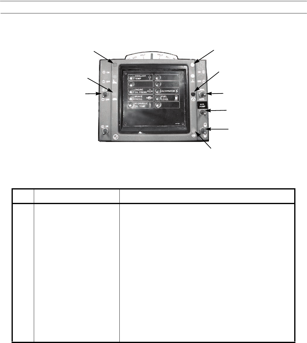
22 Blade Float Switch (if
Equipped)
With the switch in the ON position, the indicator is on and the blade
will move up and down following the contour of the ground.
23 Blade Float Indicator
(if Equipped)
With the switch in the ON position, the indicator is on.
24 Left Turn Signal Indicator With the left turn signal on, indicator will flash.
25 Right Turn Signal Indicator With the right turn signal on, indicator will flash.
26 Supplemental Steering Indicator Indicator light is on when system is working.
27 Supplemental Steering Switch Supplemental steering provides steering control if engine stalls.
Switch must be in AUTO position while operating machine.
28 Auxiliary Hydraulic Pump
Switch (if Equipped)
Used during sectionalization to allow hydraulic system control.
29 Differential Lock Switch Locks and unlocks the differential.
30 Differential Lock Indicator The indicator light is on when the differential is unlocked.
25
26
27
29
30
22
23
24
397-930
28
Contents Summary of Caterpillar GRADER, ROAD, MOTORIZED, DIESEL ENGINE DRIVEN (DED), HEAVY, COMMERCIAL CONSTRUCTION EQUIPMENT (CCE) OPERATORS MANUAL
- Page 1*TM 5-3805-261-10 TECHNICAL MANUAL OPERATOR’S MANUAL FOR GRADER, ROAD, MOTORIZED, DIESEL ENGINE DRIVEN (DED), HEAVY, COMMERCIAL CONSTRUCTION EQUIPMENT (CCE) (NSN 3805-01-150-4795) CATERPILLAR MODEL 130G (EIC: EHF) TYPE I, NONSECTIONALIZED (NSN 3805-01-126-7894) CATERPILLAR MODEL 130GNS (EIC: EHN) (N
- Page 2only Left Blank. This page is blank.
- Page 3TM 5-3805-261-10 WARNING SUMMARY This warning summary contains general safety warnings and hazardous materials warnings that must be understood and applied during operation and maintenance of this equipment. Failure to observe these precautions could result in serious injury or death to personnel. A
- Page 4TM 5-3805-261-10 HEAVY PARTS - heavy object on human figure shows that heavy parts present a danger to life or limb. HOT AREA - hand over object radiating heat shows that part is hot and can burn. HYDRAULIC FLUID PRESSURE - hydraulic fluid spraying human figure shows that fluid escaping under great
- Page 5TM 5-3805-261-10 FOR INFORMATION ON FIRST AID, REFER TO FM 4-25.11. WARNING CARBON MONOXIDE (EXHAUST GASES) CAN KILL! • Carbon monoxide is a colorless, odorless, deadly poison which, when breathed, deprives the body of oxygen and causes suffocation. Exposure to air containing carbon monoxide produce
- Page 6TM 5-3805-261-10 WARNING BATTERIES • To avoid injury, eye protection and acid-resistant gloves must be worn when working around batteries. DO NOT smoke, use open flame, make sparks, or create other ignition sources around batteries. If a battery is giving off gases, it can explode and cause injury t
- Page 7TM 5-3805-261-10 WARNING FUEL HANDLING • DO NOT smoke or permit any open flame in area of grader while you are servicing fuel system. Be sure hose nozzle is grounded against filler tube during refueling to prevent static electricity. Failure to follow this warning may result in injury to personnel o
- Page 8TM 5-3805-261-10 WARNING MACHINE OPERATION • Use caution and maintain three-point contact at all times when mounting or dismounting machine. DO NOT use steering wheel as a handhold. Failure to follow this warning may result in injury or death to personnel. • BE ALERT for personnel in the area while
- Page 9TM 5-3805-261-10 WARNING PRESSURIZED COOLING SYSTEM • DO NOT service cooling system unless engine has cooled. This is a pressurized cooling system and escaping steam or hot coolant will cause serious burns. • DO NOT remove cooling system radiator cap when engine is hot. Allow engine to cool down. Lo
- Page 10TM 5-3805-261-10 WARNING TIRES • Operating machine with underinflated or defective tire may lead to tire failure and loss of traction or con- trol. Failure to follow this warning may cause damage to equipment or injury to personnel. • If tire pressure is 0 psi (0 kPa) DO NOT inflate. Notify Unit Mai
- Page 11TM 5-3805-261-10 LIST OF EFFECTIVE PAGES/WORK PACKAGES Date of issue for original manual is: Original 28 April 2006 TOTAL NUMBER OF PAGES FOR FRONT AND REAR MATTER IS 32 AND TOTAL NUMBER OF WORK PACK- AGES IS 22 CONSISTING OF THE FOLLOWING: Page/WP *Change No. No. Cover/(Back Blank) 0 a to h 0 A/(B
- Page 12
- Page 13TM 5-3805-261-10 TECHNICAL MANUAL HEADQUARTERS TM 5-3805-261-10 DEPARTMENT OF THE ARMY Washington, D.C., 28 April 2006 OPERATOR’S MANUAL FOR GRADER, ROAD, MOTORIZED DIESEL ENGINE DRIVEN (DED), HEAVY, COMMERCIAL CONSTRUCTION EQUIPMENT (CCE) (NSN 3805-01-150-4795) CATERPILLAR MODEL 130G (EIC: EHF) TYP
- Page 14TM 5-3805-261-10 Table of Contents - Continued Page Number CHAPTER 1 GENERAL INFORMATION, EQUIPMENT DESCRIPTION, AND THEORY OF OPERATION WP 0001 00 General Information . . . . . . . . . . . . . . . . . . . . . . . . . . . . . . . . . . . . . . . . . . . . . 0001 00-1 WP 0002 00 Equipment Description
- Page 15TM 5-3805-261-10 HOW TO USE THIS MANUAL NOTE If at any time you are unsure how to use this manual or you cannot locate the information you need, notify your supervisor. INTRODUCTION 1. This revised manual is designed to help you operate all models of Caterpillar 130G Series Graders and to perform op
- Page 16TM 5-3805-261-10 FEATURES OF THIS MANUAL 1. WARNINGs, CAUTIONs, NOTEs, subject headings, and other important information are highlighted in BOLD print as a visual aid. WARNING A WARNING indicates a hazard that may result in injury or death to personnel. CAUTION A CAUTION is a reminder of safety prac
- Page 17TM 5-3805-261-10 CHAPTER 1 GENERAL INFORMATION, EQUIPMENT DESCRIPTION, AND THEORY OF OPERATION
- Page 18
- Page 19TM 5-3805-261-10 GENERAL INFORMATION 0001 00 SCOPE 1. Type of Manual. This manual is for use in operating and performing operator maintenance on the 130G Series Grader. 2. Equipment Name and Model Number. Grader, Road, Motorized, Diesel Engine Driven (DED), Heavy, Commercial Construction Equipment (
- Page 20TM 5-3805-261-10 GENERAL INFORMATION - CONTINUED 0001 00 LIST OF ABBREVIATIONS/ACRONYMS 0001 00 NOTE Refer to ASME Y14.38-1999 for standard abbreviations. ABBREVIATION/ACRONYMS DEFINITION BII . . . . . . . . . . . . . . . . . . . . . . . . . . . . . . . . . . . . . . . . . . . . . . . . . . . . . .
- Page 21TM 5-3805-261-10 EQUIPMENT DESCRIPTION AND DATA 0002 00 EQUIPMENT CHARACTERISTICS, CAPABILITIES, AND FEATURES 0002 00 1. Characteristics. a. The 130G Series Grader provides the Army with the capability of rough and finished grading, low and high bank sloping, flat and V-ditching, scarifying bitumino
- Page 22TM 5-3805-261-10 EQUIPMENT DESCRIPTION AND DATA - CONTINUED 0002 00 MODEL DIFFERENCES CHART 0002 00 NOTE The following chart lists only the operational and visual differences between the five 130G models. Internal component differences are not shown in this chart. Table 1. Model Differences. MODELS
- Page 23TM 5-3805-261-10 EQUIPMENT DESCRIPTION AND DATA - CONTINUED 0002 00 LOCATION AND DESCRIPTION OF MAJOR COMPONENTS 0002 00 3 4 1 (HIDDEN) 2 5 6 8 7 397-925A KEY COMPONENT DESCRIPTION 1 Wheel Lean Lock Pin When installed, locks wheel lean cross bar to the front axle. 2 Tool Box Contains items listed on
- Page 24TM 5-3805-261-10 EQUIPMENT DESCRIPTION AND DATA - CONTINUED 0002 00 LOCATION AND DESCRIPTION OF MAJOR COMPONENTS - CONTINUED 10 11 9 18 17 16 14 13 12 15 397-926A KEY COMPONENT DESCRIPTION 9 Rear Work Light Provides light toward rear of machine. 10 Fuel Tank Fill Cap Provides a means to fill fuel ta
- Page 25TM 5-3805-261-10 EQUIPMENT DESCRIPTION AND DATA - CONTINUED 0002 00 LOCATION AND DESCRIPTION OF MAJOR COMPONENTS - CONTINUED 22 21 23 24 25 20 26 19 27 28 29 397-1043 KEY COMPONENT DESCRIPTION 19 Blackout Driving Light Used when operating in blackout mode. 20 Front Work Lights Provide light in blade
- Page 26TM 5-3805-261-10 EQUIPMENT DESCRIPTION AND DATA - CONTINUED 0002 00 LOCATION AND DESCRIPTION OF MAJOR COMPONENTS - CONTINUED 35 34 33 31 32 36 30 38 37 397-925B KEY COMPONENT DESCRIPTION 30 Front Towing Pin Attachment point for towing. 31 Scarifier Shank Rack Storage location for scarifier shanks. 3
- Page 27TM 5-3805-261-10 EQUIPMENT DESCRIPTION AND DATA - CONTINUED 0002 00 LOCATION AND DESCRIPTION OF MAJOR COMPONENTS - CONTINUED 40 41 42 (HIDDEN) 39 45 44 43 397-926B KEY COMPONENT DESCRIPTION 39 Grab Handle Provides a hand hold. 40 Engine Compartment Access Door Provides access to right side of engine
- Page 28TM 5-3805-261-10 EQUIPMENT DESCRIPTION AND DATA - CONTINUED 0002 00 LOCATION AND DESCRIPTION OF MAJOR COMPONENTS - CONTINUED 47 46 48 397-1041 KEY COMPONENT DESCRIPTION 46 Air Dryer (if Equipped) Removes moisture from air system. 47 Control Box (GS and GSCE Models) Controls rear section of machine a
- Page 29TM 5-3805-261-10 EQUIPMENT DESCRIPTION AND DATA - CONTINUED 0002 00 EQUIPMENT DATA 0002 00 Length: Overall . . . . . . . . . . . . . . . . . . . . . . . . . . . . . . . . . . . . . . . . . . . . . . . . . . . . . . . . . . . . . 27.4 ft (8.35 m) Power Section (Sectionalized) . . . . . . . . . . . .
- Page 30TM 5-3805-261-10 EQUIPMENT DESCRIPTION AND DATA - CONTINUED 0002 00 EQUIPMENT DATA - CONTINUED Tires: Type . . . . . . . . . . . . . . . . . . . . . . . . . . . . . . . . . . . . . . . . . . . . . . . . . . . . . . . . . . . . . . . Tubeless Size . . . . . . . . . . . . . . . . . . . . . . . . . . .
- Page 31TM 5-3805-261-10 THEORY OF OPERATION 0003 00 INTRODUCTION 1. The grader consists of the following functional systems: engine; power train; air and brake systems; electrical system; steering and hydraulic systems. 2. This work package explains how the systems and components of the machine work togeth
- Page 32TM 5-3805-261-10 THEORY OF OPERATION - CONTINUED 0003 00 AIR AND BRAKE SYSTEMS 0003 00 1. General. A gear-driven, two-cylinder air compressor mounted at the left forward side of the engine provides air pres- sure for the service brakes. A dual section air reservoir is connected by air lines and moun
- Page 33TM 5-3805-261-10 THEORY OF OPERATION - CONTINUED 0003 00 HYDRAULIC SYSTEM 0003 00 1. General. The hydraulic variable-displacement pump assembly is mounted under the cab and is shaft driven by the engine. The variable-displacement rear section draws oil from the hydraulic tank and provides oil flow f
- Page 34
- Page 35TM 5-3805-261-10 CHAPTER 2 OPERATION INSTRUCTIONS
- Page 36
- Page 37TM 5-3805-261-10 DESCRIPTION AND USE OF OPERATOR CONTROLS AND INDICATORS 0004 00 GENERAL Do not attempt to operate the grader until becoming familiar with the location and use of all controls and indicators. This work package describes all operator controls and indicators. OPERATOR CONTROLS AND INDI
- Page 38TM 5-3805-261-10 DESCRIPTION AND USE OF OPERATOR CONTROLS AND INDICATORS - CONTINUED 0004 00 OPERATOR CONTROLS AND INDICATORS - CONTINUED 8 9 14 10 11 13 12 397-935 KEY CONTROL OR INDICATOR FUNCTION 8 Steering Wheel Tilt Lock Rotate counter-clockwise to loosen for adjustment. Rotate clockwise to tig
- Page 39TM 5-3805-261-10 DESCRIPTION AND USE OF OPERATOR CONTROLS AND INDICATORS - CONTINUED 0004 00 ELECTRONIC MONITORING SYSTEM (EMS) PANEL 0004 00 15 16 21 17 20 19 397-930 18 KEY CONTROL OR INDICATOR FUNCTION 15 Coolant Temperature Fault Flashes on and off when engine coolant temperature is above 225ºF
- Page 40TM 5-3805-261-10 DESCRIPTION AND USE OF OPERATOR CONTROLS AND INDICATORS - CONTINUED 0004 00 ELECTRONIC MONITORING SYSTEM (EMS) PANEL - CONTINUED 24 25 26 23 22 27 28 29 30 397-930 KEY CONTROL OR INDICATOR FUNCTION 22 Blade Float Switch (if With the switch in the ON position, the indicator is on and
- Page 41TM 5-3805-261-10 DESCRIPTION AND USE OF OPERATOR CONTROLS AND INDICATORS - CONTINUED 0004 00 EARTH MOVING CONTROLS 0004 00 32 33 34 31 397-934 KEY CONTROL OR INDICATOR FUNCTION 31 Left Side Blade Control Left side blade height control has three positions: Raise: Pull lever back to raise left side of
- Page 42TM 5-3805-261-10 DESCRIPTION AND USE OF OPERATOR CONTROLS AND INDICATORS - CONTINUED 0004 00 EARTH MOVING CONTROLS - CONTINUED 36 37 38 35 39 397-931 KEY CONTROL OR INDICATOR FUNCTION 35 Blade Centershift Control Blade centershift control has three positions: Right: Pull lever back and the drawbar,
- Page 43TM 5-3805-261-10 DESCRIPTION AND USE OF OPERATOR CONTROLS AND INDICATORS - CONTINUED 0004 00 39 Right Side Blade Control Right side blade height control has three positions: Raise: Pull lever back to raise right side of blade. Hold: Center position holds blade in set position. Lower: Move lever forw
- Page 44TM 5-3805-261-10 DESCRIPTION AND USE OF OPERATOR CONTROLS AND INDICATORS - CONTINUED 0004 00 MILITARY LIGHT SWITCH AND UNLOADING VALVE 0004 00 44 45 43 47 46 397-933 KEY CONTROL OR INDICATOR FUNCTION 43 Military Light Switch Controls operation of service, blackout, parking, and instrument panel ligh
- Page 45TM 5-3805-261-10 DESCRIPTION AND USE OF OPERATOR CONTROLS AND INDICATORS - CONTINUED 0004 00 OPERATOR CONTROL PANEL 0004 00 48 49 50 53 51 52 397-936 KEY CONTROL OR INDICATOR FUNCTION 48 Front Floodlight Switch Controls floodlights located on front of operator compartment. 49 Rear Floodlight Switch
- Page 46TM 5-3805-261-10 DESCRIPTION AND USE OF OPERATOR CONTROLS AND INDICATORS - CONTINUED 0004 00 ENGINE COMPARTMENT 0004 00 55 56 54 397-937 KEY CONTROL OR INDICATOR FUNCTION 54 Engine Oil Fill Cap Remove cap to add engine oil to the engine crankcase. 55 Engine Oil Dipstick Indicates level of oil in eng
- Page 47TM 5-3805-261-10 DESCRIPTION AND USE OF OPERATOR CONTROLS AND INDICATORS - CONTINUED 0004 00 ENGINE COMPARTMENT - CONTINUED 59 60 397-939 63 62 61 KEY CONTROL OR INDICATOR FUNCTION 59 Engine Air Filter Service Indicates air cleaner air flow is adequate if indicator is yellow or green. Indicator If i
- Page 48TM 5-3805-261-10 DESCRIPTION AND USE OF OPERATOR CONTROLS AND INDICATORS - CONTINUED 0004 00 ENGINE COMPARTMENT - CONTINUED 64 65 397-940 KEY CONTROL OR INDICATOR FUNCTION 64 Fuel Tank Dipstick Indicates level of fuel in tank. Markings on dipstick are 10%, 50%, and FULL. 65 Radiator Cap Remove cap t
- Page 49TM 5-3805-261-10 DESCRIPTION AND USE OF OPERATOR CONTROLS AND INDICATORS - CONTINUED 0004 00 OIL SAMPLING VALVES 0004 00 68 69 397-942 KEY CONTROL OR INDICATOR FUNCTION 68 Engine Oil Sampling Valve Used to collect sample of engine oil. 69 Transmission Oil Sampling Used to collect sample of transmiss
- Page 50TM 5-3805-261-10 DESCRIPTION AND USE OF OPERATOR CONTROLS AND INDICATORS - CONTINUED 0004 00 ENGINE COMPARTMENT EXTERIOR CONTROLS 0004 00 71 70 72 73 397-943 KEY CONTROL OR INDICATOR FUNCTION 70 Ether Starting Aid Switch Controls ether starting aid. Ether is injected into intake at a calibrated (130
- Page 51TM 5-3805-261-10 DESCRIPTION AND USE OF OPERATOR CONTROLS AND INDICATORS - CONTINUED 0004 00 ENGINE COMPARTMENT GAUGES 0004 00 74 75 76 77 397-944 KEY CONTROL OR INDICATOR FUNCTION 74 Hour Meter Records total engine operating hours. Used to determine service intervals. 75 Engine Coolant Temperature
- Page 52TM 5-3805-261-10 DESCRIPTION AND USE OF OPERATOR CONTROLS AND INDICATORS - CONTINUED 0004 00 LOCKING PIN LOCATION 0004 00 78 397-945 79 KEY CONTROL OR INDICATOR FUNCTION 78 Pivot Locking Pin Prevents pivoting of machine during transport. Remove before operating machine. 79 Wheel Lean Locking Pin Pre
- Page 53TM 5-3805-261-10 DESCRIPTION AND USE OF OPERATOR CONTROLS AND INDICATORS - CONTINUED 0004 00 130G CCE 0004 00 81 80 82 397-1112 KEY CONTROL OR INDICATOR FUNCTION 80 Door Safety Latch, Left Side Left side catch holds door in open position. 81 Door Safety Latch, Right Side Right side catch holds door
- Page 54TM 5-3805-261-10 DESCRIPTION AND USE OF OPERATOR CONTROLS AND INDICATORS - CONTINUED 0004 00 130G CCE - CONTINUED 84 83 85 87 86 397-1113 KEY CONTROL OR INDICATOR FUNCTION 83 Panel Light Illuminates the wiper control panel. 84 Upper Windshield Wiper/ Two-speed control. Turn clockwise. Washer Control
- Page 55TM 5-3805-261-10 DESCRIPTION AND USE OF OPERATOR CONTROLS AND INDICATORS - CONTINUED 0004 00 130G CCE - CONTINUED 89 88 397-1114 KEY CONTROL OR INDICATOR FUNCTION 88 Dome Light Switch Controls the dome light. Switch has bright, off, and dim positions. 89 Dome Light Illuminates the operator compartme
- Page 56TM 5-3805-261-10 DESCRIPTION AND USE OF OPERATOR CONTROLS AND INDICATORS - CONTINUED 0004 00 130G CCE - CONTINUED 93 94 397-1116 KEY CONTROL OR INDICATOR FUNCTION 93 Front Defroster Fan Aids in cleaning frost from windshield. 94 Rear Defroster Fan Aids in cleaning frost from rear window. 0004 00-20
- Page 57TM 5-3805-261-10 DESCRIPTION AND USE OF OPERATOR CONTROLS AND INDICATORS - CONTINUED 0004 00 130G CCE - CONTINUED 397-936 96 (HIDDEN) 95 (HIDDEN) KEY CONTROL OR INDICATOR FUNCTION 95 Main Circuit Breaker Provides overload protection for the electrical system. Press to reset. 96 Battery Disconnect Sw
- Page 58
- Page 59TM 5-3805-261-10 OPERATION UNDER USUAL CONDITIONS 0005 00 GENERAL This machine has been designed to operate safely and efficiently within the limits specified in this TM. Operation beyond these limits is prohibited in accordance with AR 70-1 without written approval from: Commander, U.S. Army Tank-
- Page 60TM 5-3805-261-10 OPERATION UNDER USUAL CONDITIONS - CONTINUED 0005 00 INITIAL ADJUSTMENTS AND DAILY CHECKS - CONTINUED CAUTION The wheel lean locking pin and pivot locking pin must be removed before operating machine. Failure to fol- lowing this caution may result in damage to machine. 2. Remove whe
- Page 61TM 5-3805-261-10 OPERATION UNDER USUAL CONDITIONS - CONTINUED 0005 00 START ENGINE - CONTINUED CAUTION DO NOT crank starter motor for more than 30 seconds at a time. After 30 seconds, allow starter motor to cool for at least 2 minutes before attempting to start engine again. Excessive heating of sta
- Page 62TM 5-3805-261-10 OPERATION UNDER USUAL CONDITIONS - CONTINUED 0005 00 START ENGINE - CONTINUED CAUTION Use ether-starting aid sparingly and for cold starting purposes ONLY. Excessive ether without cranking can cause piston and ring damage. NOTE Inject ether only while cranking engine or after initia
- Page 63TM 5-3805-261-10 OPERATION UNDER USUAL CONDITIONS - CONTINUED 0005 00 OPERATE MACHINE 0005 00 WARNING • Be ALERT for personnel in the area while operating machine. Always check to ensure area is clear of personnel and obstructions before starting engine, moving machine, or moving implements. Failure
- Page 64TM 5-3805-261-10 OPERATION UNDER USUAL CONDITIONS - CONTINUED 0005 00 OPERATE MACHINE - CONTINUED 3. Stopping the Grader. a. Move the governor control lever forward to reduce engine speed. b. Apply the service brake pedal and transmission modulator pedal to stop the machine. c. Move the transmission
- Page 65TM 5-3805-261-10 OPERATION UNDER USUAL CONDITIONS - CONTINUED 0005 00 OPERATE STEERING - CONTINUED 3. In the event of steering system failure, perform the following: a. Stop machine in a safe location. b. Apply parking/emergency brake. c. Shut down engine and troubleshoot malfunction. d. DO NOT oper
- Page 66
- Page 67TM 5-3805-261-10 ADVANCED OPERATION AND OPERATOR TIPS 0006 00 SCOPE NOTE • The information in this work package is provided as a supplement to the basic operating procedures described in WP 0005 00. A thorough reading and understanding of both this work package and WP 0005 00 is essential to safe an
- Page 68TM 5-3805-261-10 ADVANCED OPERATION AND OPERATOR TIPS - CONTINUED 0006 00 TRAVELING AND EARTH MOVING OPERATIONS - CONTINUED Turning Around in Tight Areas CAUTION Watch clearance between blade and front tires while articulating machine. 1. Lean the wheels slightly in the direction of the turn (right
- Page 69TM 5-3805-261-10 ADVANCED OPERATION AND OPERATOR TIPS - CONTINUED 0006 00 TRAVELING AND EARTH MOVING OPERATIONS - CONTINUED Turning Around in Tight Areas - Continued 4. Turn the wheels to the new travel direction. Straighten the wheels after the turn is completed. 397-951 Backing Out of a Drop-off o
- Page 70TM 5-3805-261-10 ADVANCED OPERATION AND OPERATOR TIPS - CONTINUED 0006 00 TRAVELING AND EARTH MOVING OPERATIONS - CONTINUED Backing Out of a Drop-off or Ditch - Continued 3. Turn left while moving back slowly. 397-954 4. Continue to back out until the machine is completely out of the drop-off or dit
- Page 71TM 5-3805-261-10 ADVANCED OPERATION AND OPERATOR TIPS - CONTINUED 0006 00 TRAVELING AND EARTH MOVING OPERATIONS - CONTINUED Grading Around an Object - Continued NOTE Grade as close to the object as possible to minimize hand cleanup. 2. Grade close to object. 397-957 3. While traveling in a straight
- Page 72TM 5-3805-261-10 ADVANCED OPERATION AND OPERATOR TIPS - CONTINUED 0006 00 TRAVELING AND EARTH MOVING OPERATIONS - CONTINUED Grading on an “S” Curve CAUTION Do not allow the blade to contact the tires when articulating the machine. Failure to follow this caution may result in damage to the machine. 1
- Page 73TM 5-3805-261-10 ADVANCED OPERATION AND OPERATOR TIPS - CONTINUED 0006 00 TRAVELING AND EARTH MOVING OPERATIONS - CONTINUED Grading on an “S” Curve - Continued 4. Continue to grade. 397-963 Right-Hand Leveling NOTE During right-hand leveling, left lift cylin- der will be vertical and right lift cyli
- Page 74TM 5-3805-261-10 ADVANCED OPERATION AND OPERATOR TIPS - CONTINUED 0006 00 TRAVELING AND EARTH MOVING OPERATIONS - CONTINUED Right-Hand Leveling - Continued 4. Lean the wheels to the left to overcome the side draft. 397-966 5. Tip the blade to the best position for the material being worked. Start wi
- Page 75TM 5-3805-261-10 ADVANCED OPERATION AND OPERATOR TIPS - CONTINUED 0006 00 TRAVELING AND EARTH MOVING OPERATIONS - CONTINUED Right-Hand Leveling - Continued NOTE • Normally, the machine is used with the frame straight for flat blading. Articulate it to counteract side draft from heavy blade loads. Tu
- Page 76TM 5-3805-261-10 ADVANCED OPERATION AND OPERATOR TIPS - CONTINUED 0006 00 TRAVELING AND EARTH MOVING OPERATIONS - CONTINUED Left-Hand Leveling - Continued 2. Set the blade to cast material outside of the right rear wheels. 397-971 3. Set the blade horizontal at the desired depth of the cut. 397-972
- Page 77TM 5-3805-261-10 ADVANCED OPERATION AND OPERATOR TIPS - CONTINUED 0006 00 TRAVELING AND EARTH MOVING OPERATIONS - CONTINUED Left-Hand Leveling - Continued 5. Tip the blade to the best position for the material being worked. Start with the top of the blade slightly ahead of the cut- ting edge. 6. Und
- Page 78TM 5-3805-261-10 ADVANCED OPERATION AND OPERATOR TIPS - CONTINUED 0006 00 TRAVELING AND EARTH MOVING OPERATIONS - CONTINUED Right-Hand “V” Ditching - Continued 3. Raise the left lift cylinder to the high position. Angle the blade to deliver the material inside the left rear wheels. 397-975 4. Lower
- Page 79TM 5-3805-261-10 ADVANCED OPERATION AND OPERATOR TIPS - CONTINUED 0006 00 TRAVELING AND EARTH MOVING OPERATIONS - CONTINUED Right-Hand “V” Ditching - Continued 6. Keep the right front tire in the bottom of the ditch. Continue ditching to the desired depth. 397-978 Left-Hand “V” Ditching CAUTION • Ma
- Page 80TM 5-3805-261-10 ADVANCED OPERATION AND OPERATOR TIPS - CONTINUED 0006 00 TRAVELING AND EARTH MOVING OPERATIONS - CONTINUED Left-Hand “V” Ditching - Continued 3. Raise the right lift cylinder to high position Angle the blade to deliver the material inside the right rear wheels. 397-980 4. Lower the
- Page 81TM 5-3805-261-10 ADVANCED OPERATION AND OPERATOR TIPS - CONTINUED 0006 00 TRAVELING AND EARTH MOVING OPERATIONS - CONTINUED Left-Hand “V” Ditching - Continued 6. Keep the left front tire in the bottom of the ditch. Con- tinue ditching to the desired depth. 397-982 Ditch Back Sloping CAUTION Make sur
- Page 82TM 5-3805-261-10 ADVANCED OPERATION AND OPERATOR TIPS - CONTINUED 0006 00 TRAVELING AND EARTH MOVING OPERATIONS - CONTINUED Ditch Back Sloping - Continued 6. Set the heel of the blade in front of the right rear tire. 7. Lower the right lift cylinder to set the degree of slope. NOTE The wheels should
- Page 83TM 5-3805-261-10 ADVANCED OPERATION AND OPERATOR TIPS - CONTINUED 0006 00 TRAVELING AND EARTH MOVING OPERATIONS - CONTINUED Right-Hand Ditch Cleanup - Continued 4. Set the left lift cylinder to deliver the material onto the slope between the tandems, without cutting. 397-987 5. Lean the front wheels
- Page 84TM 5-3805-261-10 ADVANCED OPERATION AND OPERATOR TIPS - CONTINUED 0006 00 TRAVELING AND EARTH MOVING OPERATIONS - CONTINUED Left-Hand Ditch Cleanup CAUTION Make sure the blade is lowered to the ground before retracting the centershift lock pin. Failure to follow this caution may result in damage to
- Page 85TM 5-3805-261-10 ADVANCED OPERATION AND OPERATOR TIPS - CONTINUED 0006 00 TRAVELING AND EARTH MOVING OPERATIONS - CONTINUED Left-Hand Ditch Cleanup - Continued 5. Lean the front wheels slightly to the right. 397-993 6. Another pass is required to move the material up the slope and onto the shoulder.
- Page 86TM 5-3805-261-10 ADVANCED OPERATION AND OPERATOR TIPS - CONTINUED 0006 00 TRAVELING AND EARTH MOVING OPERATIONS - CONTINUED Right-Hand Shoulder Cleanup - Continued 3. Lower the lift cylinders so the blade is horizontal and at the desired depth of the cut. 4. Lean the front wheels slightly to the lef
- Page 87TM 5-3805-261-10 ADVANCED OPERATION AND OPERATOR TIPS - CONTINUED 0006 00 TRAVELING AND EARTH MOVING OPERATIONS - CONTINUED Left-Hand Shoulder Cleanup - Continued 3. Lower the lift cylinders until the blade is horizontal and at the desired depth of the cut. 4. Lean the front wheels slightly to the r
- Page 88TM 5-3805-261-10 ADVANCED OPERATION AND OPERATOR TIPS - CONTINUED 0006 00 TRAVELING AND EARTH MOVING OPERATIONS - CONTINUED Road Building - “V” Ditch Method 3. Level to center and perform another heavy cut. 397-1003 397-1004 4. Clean shoulder and spread to center. 397-1005 397-1006 5. Slope and bank
- Page 89TM 5-3805-261-10 ADVANCED OPERATION AND OPERATOR TIPS - CONTINUED 0006 00 TRAVELING AND EARTH MOVING OPERATIONS - CONTINUED Road Building - “V” Ditch Method - Continued 6. Ditching pass to clean and shape inside slope. 397-1009 7. Finishing shoulder pass. 397-1010 8. Level and finish. 397-1011 0006
- Page 90TM 5-3805-261-10 ADVANCED OPERATION AND OPERATOR TIPS - CONTINUED 0006 00 TRAVELING AND EARTH MOVING OPERATIONS - CONTINUED Flat Bottom Ditching 1. If no “V” ditch exists, build a “V” ditch to the desired depth of the flat bottom ditch. NOTE The shoulder slope should be flatter than normal, ending a
- Page 91TM 5-3805-261-10 ADVANCED OPERATION AND OPERATOR TIPS - CONTINUED 0006 00 TRAVELING AND EARTH MOVING OPERATIONS - CONTINUED Flat Bottom Ditching - Continued 6. Lower the right lift cylinder to set the depth of the cut. 397-1012 7. Raise the left lift cylinder to set the desired shoulder slope. 8. Le
- Page 92TM 5-3805-261-10 ADVANCED OPERATION AND OPERATOR TIPS - CONTINUED 0006 00 TRAVELING AND EARTH MOVING OPERATIONS - CONTINUED Flat Bottom Ditching - Continued 10. Set the left lift cylinder as required. 397-1016 11. Move the centershift lock pin to the far-right position. Move the centershift lock pin
- Page 93TM 5-3805-261-10 ADVANCED OPERATION AND OPERATOR TIPS - CONTINUED 0006 00 TRAVELING AND EARTH MOVING OPERATIONS - CONTINUED Road Building - Flat Bottom Ditch Method NOTE Steps in this procedure are for one side. Repeat these steps on the opposite side. 1. Flatten the inside slope. 397-1017 2. Left h
- Page 94TM 5-3805-261-10 ADVANCED OPERATION AND OPERATOR TIPS - CONTINUED 0006 00 TRAVELING AND EARTH MOVING OPERATIONS - CONTINUED Road Building - Flat Bottom Ditch Method - Continued 4. Finish the bank slope and flatten bottom ditch out. 397-1020 5. Clean the ditch and clean the inside slope. 397-1021 6.
- Page 95TM 5-3805-261-10 ADVANCED OPERATION AND OPERATOR TIPS - CONTINUED 0006 00 TRAVELING AND EARTH MOVING OPERATIONS - CONTINUED Grading in a Wet Ditch 1. Articulate the machine so the front wheels and the blade are in the ditch. Steer with the front wheels. NOTE This method may be used to avoid obstruct
- Page 96TM 5-3805-261-10 ADVANCED OPERATION AND OPERATOR TIPS - CONTINUED 0006 00 TRAVELING AND EARTH MOVING OPERATIONS - CONTINUED Grading on a 3-to-1 Slope - Continued 2. Use crab steering when the front of the machine tends to slip due to heavy side load on the blade. 397-1025 High Bank Cuts - Right Side
- Page 97TM 5-3805-261-10 ADVANCED OPERATION AND OPERATOR TIPS - CONTINUED 0006 00 TRAVELING AND EARTH MOVING OPERATIONS - CONTINUED High Bank Cuts - Right Side - Continued 4. Move the centershift lock pin to the far left position. Move the centershift lock pin lever to the INDEX and RUN position. 5. Sideshi
- Page 98TM 5-3805-261-10 ADVANCED OPERATION AND OPERATOR TIPS - CONTINUED 0006 00 TRAVELING AND EARTH MOVING OPERATIONS - CONTINUED High Bank Cuts - Right Side - Continued 9. Lower the right lift cylinder to set the desired degree of bank slope. 10. Move into the cut gradually. 397-1031 NOTE The wheels norm
- Page 99TM 5-3805-261-10 ADVANCED OPERATION AND OPERATOR TIPS - CONTINUED 0006 00 TRAVELING AND EARTH MOVING OPERATIONS - CONTINUED Extreme Side Reach CAUTION Make sure the blade is lowered to the ground before retracting the centershift lock pin. Failure to follow this caution may result in damage to machi
- Page 100
- Page 101TM 5-3805-261-10 OPERATION UNDER UNUSUAL CONDITIONS 0007 00 GENERAL WARNING This machine has been designed to operate safely and efficiently within the limits specified in this TM. Operation beyond these limits is prohibited in accordance with AR 70-1 without written approval from: Commander, U.S. A
- Page 102TM 5-3805-261-10 OPERATION UNDER UNUSUAL CONDITIONS - CONTINUED 0007 00 OPERATE IN EXTREME COLD 0007 00 1. General. Extreme cold causes many problems: a. Lubricants thicken or congeal. b. Batteries may freeze or lose their electrical efficiency. c. Electrical insulation may crack and cause short cir
- Page 103TM 5-3805-261-10 OPERATION UNDER UNUSUAL CONDITIONS - CONTINUED 0007 00 OPERATE IN EXTREME COLD - CONTINUED 7. Machine Operation. a. Test brakes and vehicle controls carefully. b. Move all implement controls slowly to warm the hydraulic oil. Cycle each control several times. Normal warm-up period in
- Page 104TM 5-3805-261-10 OPERATION UNDER UNUSUAL CONDITIONS - CONTINUED 0007 00 OPERATE IN EXTREME HEAT - CONTINUED 3. Lubrication. Lubricate according to WP 0012 00, Preventive Maintenance Checks and Services (PMCS) Introduction, with the tem- perature range that applies to the highest expected temperature
- Page 105TM 5-3805-261-10 OPERATION UNDER UNUSUAL CONDITIONS - CONTINUED 0007 00 OPERATION IN SALTWATER AREAS 0007 00 1. Keep the machine as clean as possible. Wash down with fresh water after use. 2. Inspect wiring connections closely for corrosion. 3. Keep lubrication points clean and well lubricated. OPER
- Page 106TM 5-3805-261-10 OPERATION UNDER UNUSUAL CONDITIONS - CONTINUED 0007 00 FORDING 0007 00 1. The 130G Series Grader can be forded in water depths up to 30 inches (76 cm). Observe the following precautions when fording any body of water: 2. Before Fording. a. Check the depth of the water at its deepest
- Page 107TM 5-3805-261-10 OPERATION UNDER UNUSUAL CONDITIONS - CONTINUED 0007 00 TOWING AND SPECIAL TECHNIQUES - CONTINUED Disconnecting the Parking/Emergency Brake NOTE • Because engine is not running during towing, the following machine systems will not function properly. • Service brakes will not function
- Page 108TM 5-3805-261-10 OPERATION UNDER UNUSUAL CONDITIONS - CONTINUED 0007 00 TOWING AND SPECIAL TECHNIQUES - CONTINUED Connecting the Parking/Emergency Brake WARNING Before operating the machine, connect the rotochamber for the parking/emergency brake. Failure to follow this warning may result in injury
- Page 109TM 5-3805-261-10 DECAL AND DATA PLATE GUIDE 0008 00 SCOPE NOTE Data plates shown are for the 130GS and 130GSCE models. Data plates on other models are similar. This work package includes illustrations showing the location of all decals and data plates on the machine. DECALS AND DATA PLATES 0008 00 3
- Page 110TM 5-3805-261-10 DECAL AND DATA PLATE GUIDE - CONTINUED 0008 00 DECALS AND DATA PLATES - CONTINUED 397-1037 0008 00-2
- Page 111TM 5-3805-261-10 DECAL AND DATA PLATE GUIDE - CONTINUED 0008 00 DECALS AND DATA PLATES - CONTINUED 397-1038 (TYPE II MODELS ONLY) 0008 00-3
- Page 112TM 5-3805-261-10 DECAL AND DATA PLATE GUIDE - CONTINUED 0008 00 DECALS AND DATA PLATES - CONTINUED 397-1039 0008 00-4
- Page 113TM 5-3805-261-10 DECAL AND DATA PLATE GUIDE - CONTINUED 0008 00 DECALS AND DATA PLATES - CONTINUED 397-1040 END OF WORK PACKAGE 0008 00-5
- Page 114
- Page 115TM 5-3805-261-10 CHAPTER 3 OPERATOR TROUBLESHOOTING
- Page 116
- Page 117TM 5-3805-261-10 TROUBLESHOOTING INTRODUCTION 0009 00 INTRODUCTION 1. Troubleshooting procedures are grouped by system, containing information you need to locate malfunctions. A trouble- shooting symptom index in WP 0010 00 is provided to aid in locating a malfunction or symptom and direct you to th
- Page 118
- Page 119TM 5-3805-261-10 TROUBLESHOOTING SYMPTOM INDEX 0010 00 Malfunction/Symptom Troubleshooting Procedure Page Air System and Brakes Parking/Emergency Brake Will Not Engage . . . . . . . . . . . . . . . . . . . . . . . . . . . . . . . . . . . . . . . . . . . . . . . . . . . . . . . . 0011 00-4 Parking/Em
- Page 120TM 5-3805-261-10 TROUBLESHOOTING SYMPTOM INDEX - CONTINUED 0010 00 Hydraulic System Blade Control Levers Bind . . . . . . . . . . . . . . . . . . . . . . . . . . . . . . . . . . . . . . . . . . . . . . . . . . . . . . . . . . . . . . . . . . . . . 0011 00-10 Blade Drifts After Control Lever Is Relea
- Page 121TM 5-3805-261-10 TROUBLESHOOTING PROCEDURES 0011 00 MALFUNCTION TEST OR INSPECTION CORRECTIVE ACTION EMS FAULT INDICATORS 1. EMS Coolant Temp Indicator Flashes During Operation. WARNING • DO NOT service cooling system unless engine has been allowed to cool down. This is a pressurized cooling system
- Page 122TM 5-3805-261-10 TROUBLESHOOTING PROCEDURES - CONTINUED 0011 00 MALFUNCTION TEST OR INSPECTION CORRECTIVE ACTION EMS FAULT INDICATORS - CONTINUED 1. EMS Coolant Temp Indicator Flashes 8. Check transmission oil level. If transmission oil level is low, fill During Operation - Continued. to correct lev
- Page 123TM 5-3805-261-10 TROUBLESHOOTING PROCEDURES - CONTINUED 0011 00 MALFUNCTION TEST OR INSPECTION CORRECTIVE ACTION EMS FAULT INDICATORS - CONTINUED 5. EMS Alternator Indicator Flashes During 1. Check the battery cable If corrosion is present, notify Unit Operation. connections for corrosion. Maintenan
- Page 124TM 5-3805-261-10 TROUBLESHOOTING PROCEDURES - CONTINUED 0011 00 MALFUNCTION TEST OR INSPECTION CORRECTIVE ACTION AIR SYSTEM AND BRAKES 1. Parking/Emergency Brake Will Not WARNING Engage. Park machine on level ground, stop engine, and lower blade to prevent injury to operator and/or severe damage to
- Page 125TM 5-3805-261-10 TROUBLESHOOTING PROCEDURES - CONTINUED 0011 00 MALFUNCTION TEST OR INSPECTION CORRECTIVE ACTION AIR SYSTEM AND BRAKES - CONTINUED 3. Service Brakes Do Not Operate Correctly. WARNING Park machine on level ground, stop engine, and lower blade to prevent injury to operator and/or sever
- Page 126TM 5-3805-261-10 TROUBLESHOOTING PROCEDURES - CONTINUED 0011 00 MALFUNCTION TEST OR INSPECTION CORRECTIVE ACTION ELECTRICAL SYSTEM - CONTINUED 4. Front Work Lights Inoperative. 1. Ensure STOP LIGHT or SER Select STOP LIGHT or SER DRIVE function has been DRIVE. If problem still exists, go selected on
- Page 127TM 5-3805-261-10 TROUBLESHOOTING PROCEDURES - CONTINUED 0011 00 MALFUNCTION TEST OR INSPECTION CORRECTIVE ACTION ELECTRICAL SYSTEM - CONTINUED 7. Headlight(s)/Parking Light(s) Do Not 1. Ensure SER DRIVE or PARK Select SER DRIVE or PARK. If Operate When SER DRIVE or PARK function has been selected on
- Page 128TM 5-3805-261-10 TROUBLESHOOTING PROCEDURES - CONTINUED 0011 00 MALFUNCTION TEST OR INSPECTION CORRECTIVE ACTION ELECTRICAL SYSTEM - CONTINUED 12. Defroster Fan Not Working (if Equipped). 1. Check for blown fuses at fuse If fuse is blown, request a panel (WP 0015 00). replacement fuse from Unit Main
- Page 129TM 5-3805-261-10 TROUBLESHOOTING PROCEDURES - CONTINUED 0011 00 MALFUNCTION TEST OR INSPECTION CORRECTIVE ACTION ENGINE - CONTINUED 2. Engine Cranks but Fails to Start (Operating Temperature Below 32°F [0°C]). WARNING • DO NOT perform fuel system checks, inspections, or mainte- nance while smoking o
- Page 130TM 5-3805-261-10 TROUBLESHOOTING PROCEDURES - CONTINUED 0011 00 MALFUNCTION TEST OR INSPECTION CORRECTIVE ACTION ENGINE - CONTINUED NOTE Ensure accelerator pedal is not in off position. 5. Engine Fails to Crank When Start Switch 1. Check position of battery Place battery disconnect switch Is Turned
- Page 131TM 5-3805-261-10 TROUBLESHOOTING PROCEDURES - CONTINUED 0011 00 MALFUNCTION TEST OR INSPECTION CORRECTIVE ACTION HYDRAULIC SYSTEM - CONTINUED 2. Blade Drifts After Control Lever Is 1. Check blade hydraulic lift If any damage is found, notify Released or Centered. cylinders for damage. Unit Maintenan
- Page 132TM 5-3805-261-10 TROUBLESHOOTING PROCEDURES - CONTINUED 0011 00 MALFUNCTION TEST OR INSPECTION CORRECTIVE ACTION STEERING 1. Machine Steering Excessively Slow or WARNING Intermittent to Respond. Hitch and steering movement can reduce clearances suddenly and cause injury to personnel. Stop engine bef
- Page 133TM 5-3805-261-10 TROUBLESHOOTING PROCEDURES - CONTINUED 0011 00 MALFUNCTION TEST OR INSPECTION CORRECTIVE ACTION TRANSMISSION 1. Machine Moves, as in Gear, When Shift Shut down engine and move shift Start engine. If problem still Lever Is in Neutral (N) Position. lever through all forward gears exis
- Page 134
- Page 135TM 5-3805-261-10 CHAPTER 4 OPERATOR MAINTENANCE INSTRUCTIONS
- Page 136
- Page 137TM 5-3805-261-10 PREVENTIVE MAINTENANCE CHECKS AND SERVICES (PMCS) INTRODUCTION 0012 00 GENERAL To ensure that the machine is ready for operation at all times, it must be inspected on a regular basis so that defects may be found and corrected before they result in serious damage, equipment failure,
- Page 138TM 5-3805-261-10 PREVENTIVE MAINTENANCE CHECKS AND SERVICES (PMCS) INTRODUCTION - CONTINUED 0012 00 GENERAL PMCS PROCEDURES - CONTINUED WARNING Solvent cleaning compound MIL-PRF-680 Type III is an environmentally compliant and low toxic material. However, it may be irritating to the eyes and skin. U
- Page 139TM 5-3805-261-10 PREVENTIVE MAINTENANCE CHECKS AND SERVICES (PMCS) INTRODUCTION - CONTINUED 0012 00 GENERAL PMCS PROCEDURES - CONTINUED NOTE Notify Unit Maintenance of any leaks the operator cannot fix. Leakage Definitions for PMCS Class I Leakage indicated by wetness or discoloration, but not great
- Page 140TM 5-3805-261-10 PREVENTIVE MAINTENANCE CHECKS AND SERVICES (PMCS) INTRODUCTION - CONTINUED 0012 00 GENERAL LUBRICATION PROCEDURES - CONTINUED NOTE Only lubricants authorized for use by the operator are listed in this KEY. - KEY - EXPECTED TEMPERATURES* -25°F to LUBRICANT/ REFILL +6°F to +122°F -4°F
- Page 141TM 5-3805-261-10 PREVENTIVE MAINTENANCE CHECKS AND SERVICES (PMCS) INTRODUCTION - CONTINUED 0012 00 GENERAL LUBRICATION PROCEDURES - CONTINUED Table 2. CHART A—ENGINE EXPECTED TEMPERATURES °F -70 -60 -50 -40 -30 -20 -10 0 +10 +20 +30 +40 +50 +60 +70 +80 +90 +100 +120 Lubricant °C -57 -51 -46 -40 -34
- Page 142TM 5-3805-261-10 PREVENTIVE MAINTENANCE CHECKS AND SERVICES (PMCS) INTRODUCTION - CONTINUED 0012 00 GENERAL LUBRICATION PROCEDURES - CONTINUED NOTE • The following lube points are serviced daily and weekly. • Dashed lines indicate identical items on both sides. WHEEL LEAN LEAN BAR BEARINGS BEARINGS
- Page 143TM 5-3805-261-10 PREVENTIVE MAINTENANCE CHECKS AND SERVICES (PMCS) INTRODUCTION - CONTINUED 0012 00 GENERAL LUBRICATION PROCEDURES - CONTINUED NOTE The following lube points are serviced monthly. BLADE LIFT CYLINDERS FAN BEARING TRANSMISSION AND DIFFERENTIAL HOUSING 397-1043 CENTERSHIFT TANDEM CYLIN
- Page 144
- Page 145TM 5-3805-261-10 PREVENTIVE MAINTENANCE CHECKS AND SERVICES (PMCS) 0013 00 . LOCATION ITEM TO ITEM MAN- CHECK/ NOT FULLY MISSION NO. INTERVAL HOURS SERVICE PROCEDURE CAPABLE IF: NOTE • Review all WARNINGs, CAUTIONs, and NOTEs before performing PMCS and operating the machine. • Perform all PMCS check
- Page 146TM 5-3805-261-10 PREVENTIVE MAINTENANCE CHECKS AND SERVICES (PMCS) - CONTINUED 0013 00 LOCATION ITEM TO ITEM MAN- CHECK/ NOT FULLY MISSION NO. INTERVAL HOURS SERVICE PROCEDURE CAPABLE IF: 4 Before 0.1 Hours Hydraulic a. Visually check hydraulic tank, Class III leaks are evident. Reservoir hoses, and
- Page 147TM 5-3805-261-10 PREVENTIVE MAINTENANCE CHECKS AND SERVICES (PMCS) - CONTINUED 0013 00 LOCATION ITEM TO ITEM MAN- CHECK/ NOT FULLY MISSION NO. INTERVAL HOURS SERVICE PROCEDURE CAPABLE IF: 5 Before Air Pre- cleaner WARNING • If NBC exposure is suspected, personnel wearing protective equipment should
- Page 148TM 5-3805-261-10 PREVENTIVE MAINTENANCE CHECKS AND SERVICES (PMCS) - CONTINUED 0013 00 LOCATION ITEM TO ITEM MAN- CHECK/ NOT FULLY MISSION NO. INTERVAL HOURS SERVICE PROCEDURE CAPABLE IF: 7 Before 0.1 Engine Oil a. Clean area around engine dipstick Hours Level Check and fill cap. b. Remove dipstick,
- Page 149TM 5-3805-261-10 PREVENTIVE MAINTENANCE CHECKS AND SERVICES (PMCS) - CONTINUED 0013 00 LOCATION ITEM TO ITEM MAN- CHECK/ NOT FULLY MISSION NO. INTERVAL HOURS SERVICE PROCEDURE CAPABLE IF: 9 Before Left Battery Remove compartment access lid and Compart- check the following items: ment a. Check left s
- Page 150TM 5-3805-261-10 PREVENTIVE MAINTENANCE CHECKS AND SERVICES (PMCS) - CONTINUED 0013 00 LOCATION ITEM TO ITEM MAN- CHECK/ NOT FULLY MISSION NO. INTERVAL HOURS SERVICE PROCEDURE CAPABLE IF: 11 Before Fuel Tank Filler Cap WARNING • DO NOT smoke or permit any open flame in area of machine while you are
- Page 151TM 5-3805-261-10 PREVENTIVE MAINTENANCE CHECKS AND SERVICES (PMCS) - CONTINUED 0013 00 LOCATION ITEM TO ITEM MAN- CHECK/ NOT FULLY MISSION NO. INTERVAL HOURS SERVICE PROCEDURE CAPABLE IF: 12 Before Radiator WARNING • DO NOT service cooling system unless engine has been allowed to cool down. This is
- Page 152TM 5-3805-261-10 PREVENTIVE MAINTENANCE CHECKS AND SERVICES (PMCS) - CONTINUED 0013 00 LOCATION ITEM TO ITEM MAN- CHECK/ NOT FULLY MISSION NO. INTERVAL HOURS SERVICE PROCEDURE CAPABLE IF: 13 Before Below a. Check air tanks, lines, and valves Damage that would impair Engine Com- for damaged or missin
- Page 153TM 5-3805-261-10 PREVENTIVE MAINTENANCE CHECKS AND SERVICES (PMCS) - CONTINUED 0013 00 LOCATION ITEM TO ITEM MAN- CHECK/ NOT FULLY MISSION NO. INTERVAL HOURS SERVICE PROCEDURE CAPABLE IF: 16 Before Right Engine a. Check right rear engine compart- Missing or damaged compo- Compart- ment for damaged o
- Page 154TM 5-3805-261-10 PREVENTIVE MAINTENANCE CHECKS AND SERVICES (PMCS) - CONTINUED 0013 00 LOCATION ITEM TO ITEM MAN- CHECK/ NOT FULLY MISSION NO. INTERVAL HOURS SERVICE PROCEDURE CAPABLE IF: 21 Before EMS Panel - a. Turn the battery disconnect switch Test Switch on and leave the engine off. On and b. M
- Page 155TM 5-3805-261-10 PREVENTIVE MAINTENANCE CHECKS AND SERVICES (PMCS) - CONTINUED 0013 00 LOCATION ITEM TO ITEM MAN- CHECK/ NOT FULLY MISSION NO. INTERVAL HOURS SERVICE PROCEDURE CAPABLE IF: 22 Before EMS Panel - a. Move the EMS Panel test switch to Test Switch OFF and check for the following: Off and
- Page 156TM 5-3805-261-10 PREVENTIVE MAINTENANCE CHECKS AND SERVICES (PMCS) - CONTINUED 0013 00 LOCATION ITEM TO ITEM MAN- CHECK/ NOT FULLY MISSION NO. INTERVAL HOURS SERVICE PROCEDURE CAPABLE IF: 26 Before EMS Panel - CAUTION Supplemen- Do not hold the supplemental steering switch in the manual tal Steering
- Page 157TM 5-3805-261-10 PREVENTIVE MAINTENANCE CHECKS AND SERVICES (PMCS) - CONTINUED 0013 00 LOCATION ITEM TO ITEM MAN- CHECK/ NOT FULLY MISSION NO. INTERVAL HOURS SERVICE PROCEDURE CAPABLE IF: 31 Before Lights Check operation of lights (service and Any lights do not function, if blackout lights, brake li
- Page 158TM 5-3805-261-10 PREVENTIVE MAINTENANCE CHECKS AND SERVICES (PMCS) - CONTINUED 0013 00 LOCATION ITEM TO ITEM MAN- CHECK/ NOT FULLY MISSION NO. INTERVAL HOURS SERVICE PROCEDURE CAPABLE IF: 36 Before Transmis- a. While the engine is at low idle, sion/Differ- check the transmission oil level. ential Oi
- Page 159TM 5-3805-261-10 PREVENTIVE MAINTENANCE CHECKS AND SERVICES (PMCS) - CONTINUED 0013 00 LOCATION ITEM TO ITEM MAN- CHECK/ NOT FULLY MISSION NO. INTERVAL HOURS SERVICE PROCEDURE CAPABLE IF: ENGINE IDLING 44 After Overall View NOTE Ensure machine is clean in order to facilitate performance of PMCS insp
- Page 160TM 5-3805-261-10 PREVENTIVE MAINTENANCE CHECKS AND SERVICES (PMCS) - CONTINUED 0013 00 LOCATION ITEM TO ITEM MAN- CHECK/ NOT FULLY MISSION NO. INTERVAL HOURS SERVICE PROCEDURE CAPABLE IF: 47 After 0.1 Hours Engine Oil NOTE Level Check To ensure an accurate reading, machine must be parked on level gr
- Page 161TM 5-3805-261-10 PREVENTIVE MAINTENANCE CHECKS AND SERVICES (PMCS) - CONTINUED 0013 00 LOCATION ITEM TO ITEM MAN- CHECK/ NOT FULLY MISSION NO. INTERVAL HOURS SERVICE PROCEDURE CAPABLE IF: WARNING LEFT SIDE Improperly inflated tires can cause excessive heat buildup resulting in AND REAR blowouts. Fai
- Page 162TM 5-3805-261-10 PREVENTIVE MAINTENANCE CHECKS AND SERVICES (PMCS) - CONTINUED 0013 00 LOCATION ITEM TO ITEM MAN- CHECK/ NOT FULLY MISSION NO. INTERVAL HOURS SERVICE PROCEDURE CAPABLE IF: 54 After Blade Slide Check the blade slide bushings on Blade slide bushing has Bushings both ends for excessive
- Page 163TM 5-3805-261-10 PREVENTIVE MAINTENANCE CHECKS AND SERVICES (PMCS) - CONTINUED 0013 00 LOCATION ITEM TO ITEM MAN- CHECK/ NOT FULLY MISSION NO. INTERVAL HOURS SERVICE PROCEDURE CAPABLE IF: 59 After Rollover Check ROPS for damage and loose or Loose or missing ROPS bolts Protection missing mounting bol
- Page 164TM 5-3805-261-10 PREVENTIVE MAINTENANCE CHECKS AND SERVICES (PMCS) - CONTINUED 0013 00 LOCATION ITEM TO ITEM MAN- CHECK/ NOT FULLY MISSION NO. INTERVAL HOURS SERVICE PROCEDURE CAPABLE IF: 61 After Left Rear WARNING Wheels and Improperly inflated tires can cause excessive heat buildup resulting in Ti
- Page 165TM 5-3805-261-10 PREVENTIVE MAINTENANCE CHECKS AND SERVICES (PMCS) - CONTINUED 0013 00 LOCATION ITEM TO ITEM MAN- CHECK/ NOT FULLY MISSION NO. INTERVAL HOURS SERVICE PROCEDURE CAPABLE IF: 62 After Remote Check for leaks and for missing caps Class III leaks are evident. Control on connectors. Install
- Page 166TM 5-3805-261-10 PREVENTIVE MAINTENANCE CHECKS AND SERVICES (PMCS) - CONTINUED 0013 00 LOCATION ITEM TO ITEM MAN- CHECK/ NOT FULLY MISSION NO. INTERVAL HOURS SERVICE PROCEDURE CAPABLE IF: 64 d. Locate battery cables that are (Con’t) routed into engine compartment from battery compartment. Check for
- Page 167TM 5-3805-261-10 PREVENTIVE MAINTENANCE CHECKS AND SERVICES (PMCS) - CONTINUED 0013 00 LOCATION ITEM TO ITEM MAN- CHECK/ NOT FULLY MISSION NO. INTERVAL HOURS SERVICE PROCEDURE CAPABLE IF: 66 NOTE (Con’t) • Place portable fire extinguisher within reach prior to refuel- ing. • DO NOT overfill fuel tan
- Page 168TM 5-3805-261-10 PREVENTIVE MAINTENANCE CHECKS AND SERVICES (PMCS) - CONTINUED 0013 00 LOCATION ITEM TO ITEM MAN- CHECK/ NOT FULLY MISSION NO. INTERVAL HOURS SERVICE PROCEDURE CAPABLE IF: 67 a. Check radiator for debris. (Con’t) b. Remove debris. If debris cannot be removed, notify Unit Maintenance.
- Page 169TM 5-3805-261-10 PREVENTIVE MAINTENANCE CHECKS AND SERVICES (PMCS) - CONTINUED 0013 00 LOCATION ITEM TO ITEM MAN- CHECK/ NOT FULLY MISSION NO. INTERVAL HOURS SERVICE PROCEDURE CAPABLE IF: RIGHT SIDE AND FRONT 69 After Right Rear a. Visually check tire for cuts or Tire has cuts or bulges in tread Whe
- Page 170TM 5-3805-261-10 PREVENTIVE MAINTENANCE CHECKS AND SERVICES (PMCS) - CONTINUED 0013 00 LOCATION ITEM TO ITEM MAN- CHECK/ NOT FULLY MISSION NO. INTERVAL HOURS SERVICE PROCEDURE CAPABLE IF: 73 After Air Filter a. Check for air cleaner indicator in Red band is showing. Service Indi- red range. cator b.
- Page 171TM 5-3805-261-10 PREVENTIVE MAINTENANCE CHECKS AND SERVICES (PMCS) - CONTINUED 0013 00 LOCATION ITEM TO ITEM MAN- CHECK/ NOT FULLY MISSION NO. INTERVAL HOURS SERVICE PROCEDURE CAPABLE IF: 77 After Right Door Check right door for damage or miss- Missing or damaged compo- (If equipped) ing components.
- Page 172TM 5-3805-261-10 PREVENTIVE MAINTENANCE CHECKS AND SERVICES (PMCS) - CONTINUED 0013 00 LOCATION ITEM TO ITEM MAN- CHECK/ NOT FULLY MISSION NO. INTERVAL HOURS SERVICE PROCEDURE CAPABLE IF: 82 After Cutting Edge NOTE and End Bits • If blade cutting edge or end bits are worn or damaged, notify Unit Mai
- Page 173TM 5-3805-261-10 PREVENTIVE MAINTENANCE CHECKS AND SERVICES (PMCS) - CONTINUED 0013 00 LOCATION ITEM TO ITEM MAN- CHECK/ NOT FULLY MISSION NO. INTERVAL HOURS SERVICE PROCEDURE CAPABLE IF: 88 After Right Front a. Visually check right front tire for Tire has cuts or bulges in tread Wheel and cuts or b
- Page 174TM 5-3805-261-10 PREVENTIVE MAINTENANCE CHECKS AND SERVICES (PMCS) - CONTINUED 0013 00 LOCATION ITEM TO ITEM MAN- CHECK/ NOT FULLY MISSION NO. INTERVAL HOURS SERVICE PROCEDURE CAPABLE IF: 90 Weekly 0.2 Hours Wheel Lean a. Apply GAA grease (Item 8, WP Cylinder 0022 00) to cylinder pivot bearing greas
- Page 175TM 5-3805-261-10 PREVENTIVE MAINTENANCE CHECKS AND SERVICES (PMCS) - CONTINUED 0013 00 LOCATION ITEM TO ITEM MAN- CHECK/ NOT FULLY MISSION NO. INTERVAL HOURS SERVICE PROCEDURE CAPABLE IF: 91 Weekly 0.2 Hours Scarifier and a. Apply GAA grease (Item 8, WP Drawbar 0022 00) to right upper and lower scar
- Page 176TM 5-3805-261-10 PREVENTIVE MAINTENANCE CHECKS AND SERVICES (PMCS) - CONTINUED 0013 00 LOCATION ITEM TO ITEM MAN- CHECK/ NOT FULLY MISSION NO. INTERVAL HOURS SERVICE PROCEDURE CAPABLE IF: 92 Weekly 0.2 Hours Articulation a. Apply GAA grease (Item 8, WP Pivot 0022 00) to upper articulation pivot grea
- Page 177TM 5-3805-261-10 PREVENTIVE MAINTENANCE CHECKS AND SERVICES (PMCS) - CONTINUED 0013 00 LOCATION ITEM TO ITEM MAN- CHECK/ NOT FULLY MISSION NO. INTERVAL HOURS SERVICE PROCEDURE CAPABLE IF: 93 Weekly Left Battery Compart- ment WARNING • To avoid injury, eye protection and acid-resistant gloves must be
- Page 178TM 5-3805-261-10 PREVENTIVE MAINTENANCE CHECKS AND SERVICES (PMCS) - CONTINUED 0013 00 LOCATION ITEM TO ITEM MAN- CHECK/ NOT FULLY MISSION NO. INTERVAL HOURS SERVICE PROCEDURE CAPABLE IF: 93 h. Check for rust, corrosion, and (Con’t) cleanness. i. Check battery cable grommets for dry rot and loose or
- Page 179TM 5-3805-261-10 PREVENTIVE MAINTENANCE CHECKS AND SERVICES (PMCS) - CONTINUED 0013 00 LOCATION ITEM TO ITEM MAN- CHECK/ NOT FULLY MISSION NO. INTERVAL HOURS SERVICE PROCEDURE CAPABLE IF: 95 a. Remove two bolts and open right (Con’t) rear engine access cover. b. Check for loose connections and Damag
- Page 180TM 5-3805-261-10 PREVENTIVE MAINTENANCE CHECKS AND SERVICES (PMCS) - CONTINUED 0013 00 LOCATION ITEM TO ITEM MAN- CHECK/ NOT FULLY MISSION NO. INTERVAL HOURS SERVICE PROCEDURE CAPABLE IF: 97 Weekly Right Bat- tery Com- partment WARNING • To avoid injury, eye protection and acid-resistant gloves must
- Page 181TM 5-3805-261-10 PREVENTIVE MAINTENANCE CHECKS AND SERVICES (PMCS) - CONTINUED 0013 00 LOCATION ITEM TO ITEM MAN- CHECK/ NOT FULLY MISSION NO. INTERVAL HOURS SERVICE PROCEDURE CAPABLE IF: 97 h. Check for rust, corrosion, and (Con’t) cleanliness. i. Check battery cable grommets for dry rot, looseness
- Page 182TM 5-3805-261-10 PREVENTIVE MAINTENANCE CHECKS AND SERVICES (PMCS) - CONTINUED 0013 00 LOCATION ITEM TO ITEM MAN- CHECK/ NOT FULLY MISSION NO. INTERVAL HOURS SERVICE PROCEDURE CAPABLE IF: 101 Weekly Wheels and a. Check for loose or missing lug Missing two or more lug nuts Tires nuts or valve stem ca
- Page 183TM 5-3805-261-10 PREVENTIVE MAINTENANCE CHECKS AND SERVICES (PMCS) - CONTINUED 0013 00 LOCATION ITEM TO ITEM MAN- CHECK/ NOT FULLY MISSION NO. INTERVAL HOURS SERVICE PROCEDURE CAPABLE IF: 102 Monthly 0.2 Hours Blade Lift a. Apply GAA grease (Item 8, WP and Center- 0022 00) to blade lift cylinder shi
- Page 184TM 5-3805-261-10 PREVENTIVE MAINTENANCE CHECKS AND SERVICES (PMCS) - CONTINUED 0013 00 LOCATION ITEM TO ITEM MAN- CHECK/ NOT FULLY MISSION NO. INTERVAL HOURS SERVICE PROCEDURE CAPABLE IF: 104 Monthly Drive Belts a. Remove two bolts and open left rear engine compartment access door. b. Check belts fo
- Page 185TM 5-3805-261-10 PREVENTIVE MAINTENANCE CHECKS AND SERVICES (PMCS) - CONTINUED 0013 00 LOCATION ITEM TO ITEM MAN- CHECK/ NOT FULLY MISSION NO. INTERVAL HOURS SERVICE PROCEDURE CAPABLE IF: 105 Monthly All Systems - CAUTION Machine DO NOT perform this PMCS exercise when temperature is Exercise below 0
- Page 186TM 5-3805-261-10 PREVENTIVE MAINTENANCE CHECKS AND SERVICES (PMCS) - CONTINUED 0013 00 LOCATION ITEM TO ITEM MAN- CHECK/ NOT FULLY MISSION NO. INTERVAL HOURS SERVICE PROCEDURE CAPABLE IF: 105 i. Move machine and continue to (Con’t) operate all controls through full motion for 30 minutes AFTER machin
- Page 187TM 5-3805-261-10 PREVENTIVE MAINTENANCE CHECKS AND SERVICES (PMCS) - CONTINUED 0013 00 LOCATION ITEM TO ITEM MAN- CHECK/ NOT FULLY MISSION NO. INTERVAL HOURS SERVICE PROCEDURE CAPABLE IF: 107 Monthly Parking WARNING Brake Test Be ALERT for personnel in the area while operating machine. Always check
- Page 188TM 5-3805-261-10 PREVENTIVE MAINTENANCE CHECKS AND SERVICES (PMCS) - CONTINUED 0013 00 LOCATION ITEM TO ITEM MAN- CHECK/ NOT FULLY MISSION NO. INTERVAL HOURS SERVICE PROCEDURE CAPABLE IF: 108 e. Remove two bolts from control (Con’t) box cover and remove cover. f. Check controls for damage and debris
- Page 189TM 5-3805-261-10 ENGINE AIR PRECLEANER AND AIR CLEANER ASSEMBLY SERVICING 0014 00 THIS WORK PACKAGE COVERS Engine Air Precleaner Inspection Engine Air Cleaner Assembly Servicing INITIAL SETUP Materials/Parts Equipment Condition Detergent (Item 4, WP 0022 00) Engine off Rag, wiping (Item 15, WP 0022
- Page 190TM 5-3805-261-10 ENGINE AIR PRECLEANER AND AIR CLEANER ASSEMBLY SERVICING - CONTINUED 0014 00 ENGINE AIR CLEANER ASSEMBLY SERVICING 0014 00 1. Loosen two eyebolts and remove cover. 2. Inspect cover seal for damage. If damaged, notify Unit Maintenance to obtain replacement cover and/or seal. EYEBOLTS
- Page 191TM 5-3805-261-10 ENGINE AIR PRECLEANER AND AIR CLEANER ASSEMBLY SERVICING - CONTINUED 0014 00 ENGINE AIR CLEANER ASSEMBLY SERVICING - CONTINUED NOTE A primary element may be cleaned a maximum of six times. Also replace primary element if it has been in service for one year. SECONDARY ELEMENT PRIMARY
- Page 192TM 5-3805-261-10 ENGINE AIR PRECLEANER AND AIR CLEANER ASSEMBLY SERVICING - CONTINUED 0014 00 ENGINE AIR CLEANER ASSEMBLY SERVICING - CONTINUED NOTE Primary element must be completely dry before installation. 9. Install primary element inside air cleaner housing. SECONDARY ELEMENT PRIMARY ELEMENT AI
- Page 193TM 5-3805-261-10 ENGINE AIR PRECLEANER AND AIR CLEANER ASSEMBLY SERVICING - CONTINUED 0014 00 ENGINE AIR CLEANER ASSEMBLY SERVICING - CONTINUED 11. Reset air filter service indicator by pushing in on bottom of indicator. AIR FILTER SERVICE INDICATOR 397-1051 12. Start engine. 13. If air filter servi
- Page 194
- Page 195TM 5-3805-261-10 FUSE REPLACEMENT 0015 00 THIS WORK PACKAGE COVERS Removal, Installation INITIAL SETUP Materials/Parts Equipment Conditions - Continued Fuse Machine parked on level ground Equipment Conditions Parking/emergency brake applied (WP 0004 00) Machine parked on level ground Implements lowe
- Page 196TM 5-3805-261-10 FUSE REPLACEMENT - CONTINUED 0015 00 INSTALLATION CAUTION Always verify amperage rating of new fuse is correct. Using a fuse with the wrong amperage could result in damage to electrical system. 1. Install new fuse in fuse box. 2. Close fuse panel cover. 3. Turn on the battery discon
- Page 197TM 5-3805-261-10 FUSE REPLACEMENT - CONTINUED 0015 00 INSTALLATION - CONTINUED Fuse Chart - 130G CCE Model FUSE AMPERAGE COMPONENT 1 4 (slow blow) Front Wiper 2 15 Heater/Air Conditioner 3 10 Beacon 4 10 Fan (Rear) 5 5 Dome Light 6 4 (slow blow) Rear Wiper 7 15 Lighter 8 Spare 1 2 3 4 5 6 7 8 397-11
- Page 198
- Page 199TM 5-3805-261-10 TIRE MAINTENANCE 0016 00 THIS WORK PACKAGE COVERS Tire Pressure Adjustment INITIAL SETUP Tools and Special Tools Equipment Conditions Gauge, tire pressure (Item 8, WP 0021 00) Machine parked on level ground Hose assembly, pneumatic: tire inflation (Item 10, Parking/emergency brake a
- Page 200TM 5-3805-261-10 TIRE MAINTENANCE - CONTINUED 0016 00 TIRE PRESSURE ADJUSTMENT VALVE STEM AND CAP 397-1046 1. Remove valve stem cap. 2. Check tire pressure with tire pressure gauge. Correct pressure is 35 psi (241 kpa) for all tires on the 130G. 3. Attach air chuck to the valve stem. 4. Stand at tre
- Page 201TM 5-3805-261-10 PREPARATION FOR TRANSPORT INTRODUCTION 0017 00 GENERAL 1. Check the regulations covering transportation of cylinders containing compressed gas. 2. Check the travel route for overpass clearances. Be sure that there will be adequate clearance for the Rollover Protective Structure (ROP
- Page 202
- Page 203TM 5-3805-261-10 SECTIONALIZATION FOR AIR TRANSPORT INTRODUCTION 0018 00 INTRODUCTION There are two models of the 130G Type II (130GS and 130GSCE) that can be sectionalized and transported by helicop- ter. These machines are equipped with all special tools and equipment needed for sectionalization.
- Page 204TM 5-3805-261-10 SECTIONALIZATION FOR AIR TRANSPORT INTRODUCTION - CONTINUED 0018 00 TOOLS AND EQUIPMENT 1. Tools and equipment required for sectionalization are stored in a tool box located on the front of the machine. 2. BII tools (WP 0021 00) must also be used. 3. The following table contains wre
- Page 205TM 5-3805-261-10 SECTIONALIZATION FOR AIR TRANSPORT 0019 00 THIS WORK PACKAGE COVERS Disassembly, Driving the Rear Frame, Assembly INITIAL SETUP Tools and Special Tools Personnel Components of End Item and Basic Issue Items Two (WP 0021 00) Equipment Conditions Materials/Parts Rag, wiping (Item 15,
- Page 206TM 5-3805-261-10 SECTIONALIZATION FOR AIR TRANSPORT - CONTINUED 0019 00 DISASSEMBLY - CONTINUED 7. Remove three bolts (1) and washers (2) from top of hydraulic pump driveshaft guards (3). 8. Remove four bolts (4), washers (5), and two hydraulic pump driveshaft guards (3). 1,2 3 4,5 397-1066 9. Remov
- Page 207TM 5-3805-261-10 SECTIONALIZATION FOR AIR TRANSPORT - CONTINUED 0019 00 DISASSEMBLY - CONTINUED 12. Install the pump driveshaft lock bar on pump yoke using two driveshaft bolts (6). Be sure that free end of lock bar is pointing toward right hand side of machine. Lock bar will prevent pump rotation.
- Page 208TM 5-3805-261-10 SECTIONALIZATION FOR AIR TRANSPORT - CONTINUED 0019 00 DISASSEMBLY - CONTINUED 14. Remove four bolts (18), washers (19), and two retainer caps (20) from right articulation cylinder (21). 18,19 20 397-1124 21 20 18,19 15. Remove three bolts (22), washers (23), and cap (24) from the b
- Page 209TM 5-3805-261-10 SECTIONALIZATION FOR AIR TRANSPORT - CONTINUED 0019 00 DISASSEMBLY - CONTINUED 16. Loosen six retainer bolts (25) on the bottom of lower pivot pin (26) about 1/2 in. 397-1101 26 25 0019 00-5
- Page 210TM 5-3805-261-10 SECTIONALIZATION FOR AIR TRANSPORT - CONTINUED 0019 00 DISASSEMBLY - CONTINUED • DO NOT disconnect or remove any hydraulic system hose or fitting unless engine is shut down and hydraulic system pressure has been relieved. Tighten all connections before applying pressure. Escap- ing
- Page 211TM 5-3805-261-10 SECTIONALIZATION FOR AIR TRANSPORT - CONTINUED 0019 00 DISASSEMBLY - CONTINUED 19. Disconnect hydraulic hose (32) and three air hoses (33, 34, and 35) on right side of machine. 32 35 34 33 397-1071 20. Remove dirt from dust covers and install on connectors. NOTE The following step i
- Page 212TM 5-3805-261-10 SECTIONALIZATION FOR AIR TRANSPORT - CONTINUED 0019 00 DISASSEMBLY - CONTINUED NOTE • When disconnecting cables, move the appropriate control lever in operator compartment as needed to aid in disconnection. • Tag cables to assist in connecting to remote control box and when returnin
- Page 213TM 5-3805-261-10 SECTIONALIZATION FOR AIR TRANSPORT - CONTINUED 0019 00 DISASSEMBLY - CONTINUED NOTE Tag cables to assist in connecting to remote control box and when returning to normal configuration. 25. Disconnect clutch cable (42) on left side of machine and install dust cover. Tag both cable en
- Page 214TM 5-3805-261-10 SECTIONALIZATION FOR AIR TRANSPORT - CONTINUED 0019 00 DISASSEMBLY - CONTINUED 30. Pull all hoses, cables, and wiring harness through platform supports on both sides of machine. WARNING Wear eye protection when disconnecting hydraulic hoses. Failure to follow this warning may cause
- Page 215TM 5-3805-261-10 SECTIONALIZATION FOR AIR TRANSPORT - CONTINUED 0019 00 DISASSEMBLY - CONTINUED 34. Remove two cotter pins (55) and pins (53) from both ends of articulation indicator connecting rod (54). Discard cotter pins. 35. Place articulation indicator connecting rod (54) and pins (53) in front
- Page 216TM 5-3805-261-10 SECTIONALIZATION FOR AIR TRANSPORT - CONTINUED 0019 00 DISASSEMBLY - CONTINUED 37. Connect jumper hose (58) to auxiliary pump supply hose (27) on left side of machine. 38. Connect other end of jumper hose (58) to auxiliary pump supply connector (57). 57 27 58 397-1104 39. Connect ju
- Page 217TM 5-3805-261-10 SECTIONALIZATION FOR AIR TRANSPORT - CONTINUED 0019 00 DISASSEMBLY - CONTINUED 41. Connect electrical jumper harness between engine connector (62) and platform connector (61). 61 397-1080 62 (HIDDEN) 42. Position two screw jacks (63) over mounting holes on 63 64 each side of rear fr
- Page 218TM 5-3805-261-10 SECTIONALIZATION FOR AIR TRANSPORT - CONTINUED 0019 00 DISASSEMBLY - CONTINUED 44. Disconnect rear electrical harness (66) and pull through frame to under operator compartment. Secure harness to machine. 66 397-1110 CAUTION Carefully remove articulation cylinder pins to avoid damage
- Page 219TM 5-3805-261-10 SECTIONALIZATION FOR AIR TRANSPORT - CONTINUED 0019 00 DISASSEMBLY - CONTINUED CAUTION DO NOT turn on auxiliary pump for more than 30 seconds. Allow pump to cool for 1 minute between each use. NOTE To relieve load on hitch, turn on battery disconnect switch, turn on auxiliary pump s
- Page 220TM 5-3805-261-10 SECTIONALIZATION FOR AIR TRANSPORT - CONTINUED 0019 00 DISASSEMBLY - CONTINUED 70,71 WARNING 72 Use extreme caution when handling heavy parts. Provide adequate support and use assistance during procedure. Failure to fol- low this warning may result in injury to personnel. NOTE Remot
- Page 221TM 5-3805-261-10 SECTIONALIZATION FOR AIR TRANSPORT - CONTINUED 0019 00 DISASSEMBLY - CONTINUED NOTE To aid in clutch cable connection, press button on remote control box clutch control to allow cable to move freely. 59. Connect remote control cables to machine cables (use tags added during removal)
- Page 222TM 5-3805-261-10 SECTIONALIZATION FOR AIR TRANSPORT - CONTINUED 0019 00 DISASSEMBLY - CONTINUED 68. Install shield (77) and three clips (78) on rear section. 77 78 78 397-1106 69. Secure hoses and cables to tandems and strap articulation cylinders to rear frame. 70. Secure hoses and cables to front
- Page 223TM 5-3805-261-10 SECTIONALIZATION FOR AIR TRANSPORT - CONTINUED 0019 00 DISASSEMBLY - CONTINUED NOTE 40,41,42 75 76 • At this point, the rear frame can be driven to air lift slinging location. • Before slinging, proceed with the remaining disassembly steps. 76. Disconnect remote control hoses (76) a
- Page 224TM 5-3805-261-10 SECTIONALIZATION FOR AIR TRANSPORT - CONTINUED 0019 00 DISASSEMBLY - CONTINUED 82. Install two bolts (70) and nuts (71) on remote control box (72). 70,71 83. Install two straps (Item 20, WP 0021 00) on remote control box hoses and cables. 72 84. Store the articulation cylinder pins,
- Page 225TM 5-3805-261-10 SECTIONALIZATION FOR AIR TRANSPORT - CONTINUED 0019 00 DRIVING THE REAR FRAME - CONTINUED WARNING • Stop the unit immediately if the LOW AIR indicator light illuminates. Determine the source of the prob- lem and correct before continuing operation. The LOW AIR light will come on mom
- Page 226TM 5-3805-261-10 SECTIONALIZATION FOR AIR TRANSPORT - CONTINUED 0019 00 DRIVING THE REAR FRAME - CONTINUED 5. Turning the machine: NOTE The directions LEFT and RIGHT in this procedure relate to the direction of travel. a. While moving the machine in a forward direction, pull the steering control tow
- Page 227TM 5-3805-261-10 SECTIONALIZATION FOR AIR TRANSPORT - CONTINUED 0019 00 ASSEMBLY - CONTINUED 3. Install remote control box (72) in bracket near left- 73 hand battery box. 4. Remove two bolts (73) and cover (74) from remote 74 control box (72). 72 397-1084 5. Remove dust covers from the cables and ho
- Page 228TM 5-3805-261-10 SECTIONALIZATION FOR AIR TRANSPORT - CONTINUED 0019 00 ASSEMBLY - CONTINUED 8. Engage the parking/emergency brake, shift the transmission to Neutral and disengage the clutch. See Driving the Rear Frame in this work package. 9. Start the engine and move the rear frame to within 3 ft.
- Page 229TM 5-3805-261-10 SECTIONALIZATION FOR AIR TRANSPORT - CONTINUED 0019 00 ASSEMBLY - CONTINUED 21. Remove four bolts (10), washers (11), and upper pivot pin (9) from front section. 22. Remove six bolts (25), retainer (56), bolts (68), washers (69), and lower pivot pin (26) from the rear section. 68,69
- Page 230TM 5-3805-261-10 SECTIONALIZATION FOR AIR TRANSPORT - CONTINUED 0019 00 ASSEMBLY - CONTINUED 25. Connect jumper hose (60) to auxiliary pump return hose (32) on right side of machine. 26. Connect other end of jumper hose (60) to tank hose connector (59). 59 32 60 397-1105 27. Connect electrical jumpe
- Page 231TM 5-3805-261-10 SECTIONALIZATION FOR AIR TRANSPORT - CONTINUED 0019 00 ASSEMBLY - CONTINUED Keep all personnel away from machine while rear section is moving and while adjusting blade. Failure to follow this warning may cause injury or death to personnel. CAUTION DO NOT turn on auxiliary pump for m
- Page 232TM 5-3805-261-10 SECTIONALIZATION FOR AIR TRANSPORT - CONTINUED 0019 00 ASSEMBLY - CONTINUED NOTE During retainer installation, position two bolts through holes to hold and align the shims. 33. Install shims, retainer (56), and six bolts (25) on bottom of lower pivot pin (26). Gradually tighten bolt
- Page 233TM 5-3805-261-10 SECTIONALIZATION FOR AIR TRANSPORT - CONTINUED 0019 00 ASSEMBLY - CONTINUED NOTE The holes in the sides of the pivot pin cap must face the sides of the machine for mounting the pump drive- shaft guard, and the grease fitting must face the right side. 36. Install upper pivot pin (9),
- Page 234TM 5-3805-261-10 SECTIONALIZATION FOR AIR TRANSPORT - CONTINUED 0019 00 ASSEMBLY - CONTINUED WARNING Wear eye protection when connecting pressurized hoses. Failure to follow this warning may cause injury to personnel. 40. Disconnect two hydraulic jumper hoses and electrical jumper harness. Install p
- Page 235TM 5-3805-261-10 SECTIONALIZATION FOR AIR TRANSPORT - CONTINUED 0019 00 ASSEMBLY - CONTINUED 44. Disconnect remote control hoses (76), electrical con- 75 76 nector (75), and cables of the remote control box (72). Install dust plugs on all connections. 72 397-1085 45. Install cover (74) and two bolts
- Page 236TM 5-3805-261-10 SECTIONALIZATION FOR AIR TRANSPORT - CONTINUED 0019 00 ASSEMBLY - CONTINUED 49. Remove two spring clips (65), pins (64), and screw 63 64 jack (63) from each side of rear frame and store in the 65 tool box. 397-1081 50. Install articulation indicator connecting rod (54), two pins (53
- Page 237TM 5-3805-261-10 SECTIONALIZATION FOR AIR TRANSPORT - CONTINUED 0019 00 ASSEMBLY - CONTINUED WARNING Wear eye protection when connecting pressurized hoses. Failure to follow this warning may cause injury to personnel. NOTE • If trouble is experienced when attempting to connect articulation cylinder
- Page 238TM 5-3805-261-10 SECTIONALIZATION FOR AIR TRANSPORT - CONTINUED 0019 00 ASSEMBLY - CONTINUED NOTE Remove caps to make connections. Connect caps together when not in use. 52. Feed hoses between platform support and frame. 53. Connect air hoses (30 and 31) and hydraulic hoses (27, 28, and 29) on the l
- Page 239TM 5-3805-261-10 SECTIONALIZATION FOR AIR TRANSPORT - CONTINUED 0019 00 ASSEMBLY - CONTINUED NOTE Remove caps to make connections. Connect caps together when not in use. 55. Feed hoses between platform support and frame. 56. Connect air hoses (33, 35, and 39) and hydraulic hose (32) on right side of
- Page 240TM 5-3805-261-10 SECTIONALIZATION FOR AIR TRANSPORT - CONTINUED 0019 00 ASSEMBLY - CONTINUED 58. Connect two transmission cables (40 and 41) on right side of machine. 40 41 397-1073 59. Remove bolt (46), washer (47), and clamp (48) from right side of machine. 60. Install clamp (48), washer (47), and
- Page 241TM 5-3805-261-10 SECTIONALIZATION FOR AIR TRANSPORT - CONTINUED 0019 00 ASSEMBLY - CONTINUED 62. Install clamp (38), washers (37), and nuts (36) on each side of machine. 36,37 38 36,37 397-1072 63. Route rear electrical harness (66) through to rear of machine and connect to rear harness connector. 6
- Page 242TM 5-3805-261-10 SECTIONALIZATION FOR AIR TRANSPORT - CONTINUED 0019 00 ASSEMBLY - CONTINUED 64. Turn on battery disconnect switch and start the engine (WP 0005 00). Align articulation cylinder eyes with holes in frame and install cylinder pin (67) on each side of the machine. 67 397-1082 65. Shut d
- Page 243TM 5-3805-261-10 SECTIONALIZATION FOR AIR TRANSPORT - CONTINUED 0019 00 ASSEMBLY - CONTINUED 67. Install two retainer caps (20), four washers (19), and bolts (18) on right articulation cylinders (21). 18,19 20 397-1124 21 20 18,19 68. Store all tools, jumpers, and all other equipment in the tool box
- Page 244
- Page 245TM 5-3805-261-10 CHAPTER 5 SUPPORTING INFORMATION
- Page 246
- Page 247TM 5-3805-261-10 REFERENCES 0020 00 SCOPE This work package lists all publication indexes, forms, field manuals, technical manuals, and other publications refer- enced in this manual and which apply to operation and operator maintenance of the 130G Series Grader. PUBLICATION INDEXES The following in
- Page 248TM 5-3805-261-10 REFERENCES - CONTINUED 0020 00 TECHNICAL MANUALS Operator’s, Unit, Direct Support, and General Support Maintenance Manual for Lead-Acid Storage Batteries . . . . . . . . . . . . . . . . . . . . . . . . . . . . . . . . . . . . . . . . . . . . . . . . . TM 9-6140-200-14 Operator’s, Un
- Page 249TM 5-3805-261-10 COMPONENTS OF END ITEM (COEI) AND BASIC ISSUE ITEMS (BII) LISTS 0021 00 SCOPE This work package lists COEI and BII for the 130G Series Grader, to help you inventory items required for safe and effi- cient operation. GENERAL The COEI and BII information is divided into the following
- Page 250TM 5-3805-261-10 COMPONENTS OF END ITEM (COEI) AND BASIC ISSUE ITEMS (BII) LISTS - CONTINUED 0021 00 Table 1. Components of End Item List . (1) (2) (3) (4) (5) (6) ILLUS NATIONAL STOCK DESCRIPTION, CAGEC, USABLE QTY NUMBER NUMBER AND PART NUMBER ON CODE U/M RQD 1 5306-00-260-4508 BOLT, MACHINE AF10,
- Page 251TM 5-3805-261-10 COMPONENTS OF END ITEM (COEI) AND BASIC ISSUE ITEMS (BII) LISTS - CONTINUED 0021 00 Table 1. Components of End Item List - Continued. (1) (2) (3) (4) (5) (6) ILLUS NATIONAL STOCK DESCRIPTION, CAGEC, USABLE QTY NUMBER NUMBER AND PART NUMBER ON CODE U/M RQD 17 5365-01-169-8377 RETAINE
- Page 252TM 5-3805-261-10 COMPONENTS OF END ITEM (COEI) AND BASIC ISSUE ITEMS (BII) LISTS - CONTINUED 0021 00 Table 2. Basic Issue Items List. (1) (2) (3) (4) (5) (6) ILLUS NATIONAL STOCK DESCRIPTION, CAGEC, USABLE QTY NUMBER NUMBER AND PART NUMBER ON CODE U/M RQD 1 4930-00-288-1511 ADAPTER, GREASE GUN COUPL
- Page 253TM 5-3805-261-10 EXPENDABLE AND DURABLE ITEMS LIST 0022 00 SCOPE This work package lists expendable and durable items you will need to operate and maintain the 130G Series Grader. This listing is for informational purposes only and is not authority to requisition the listed items. These items are au
- Page 254TM 5-3805-261-10 EXPENDABLE AND DURABLE ITEMS LIST - CONTINUED 0022 00 . (1) (2) (3) (4) (5) ITEM NATIONAL DESCRIPTION, CAGEC, NUMBER LEVEL STOCK NUMBER AND PART NUMBER U/M 1 C ANTIFREEZE: Permanent Ethylene Glycol, Inhibited, Heavy-Duty 6850-01-441-3218 (58536) A-A-52624 1 Gallon Can CN 6850-00-181
- Page 255TM 5-3805-261-10 EXPENDABLE AND DURABLE ITEMS LIST - CONTINUED 0022 00 (1) (2) (3) (4) (5) ITEM NATIONAL DESCRIPTION, CAGEC, NUMBER LEVEL STOCK NUMBER AND PART NUMBER U/M 8 C GREASE: Automotive and Artillery GAA 9150-01-197-7688 (81349) M-10924-A 1-1/4 Ounce Tube TU 9150-01-197-7693 (81349) M-10924-
- Page 256TM 5-3805-261-10 EXPENDABLE AND DURABLE ITEMS LIST - CONTINUED 0022 00 (1) (2) (3) (4) (5) ITEM NATIONAL DESCRIPTION, CAGEC, NUMBER LEVEL STOCK NUMBER AND PART NUMBER U/M 15 C RAG: Wiping (64067) 7920-00-205-1711 7920-00-205-1711 50 Pound Bale BL 16 C TAG, MARKER (64067) 9905-00-537-8954 9905-00-537
- Page 257TM 5-3805-261-23 INDEX Subject Work Package/Page A Abbreviations/Acronyms, List of . . . . . . . . . . . . . . . . . . . . . . . . . . . . . . . . . . . . . . . . . . . . . . . . 0001 00-2 After Operation . . . . . . . . . . . . . . . . . . . . . . . . . . . . . . . . . . . . . . . . . . . . . . . .
- Page 258TM 5-3805-261-23 INDEX - Continued Subject Work Package/Page H Hydraulic System, Theory of Operation . . . . . . . . . . . . . . . . . . . . . . . . . . . . . . . . . . . . . . . . . . 0003 00-3 I Initial Adjustments and Daily Checks . . . . . . . . . . . . . . . . . . . . . . . . . . . . . . . . .
- Page 259TM 5-3805-261-23 INDEX - Continued Subject Work Package/Page P Power Train, Theory of Operation . . . . . . . . . . . . . . . . . . . . . . . . . . . . . . . . . . . . . . . . . . . . . . . 0003 00-1 Preparation for Shipment . . . . . . . . . . . . . . . . . . . . . . . . . . . . . . . . . . . . . .
- Page 260
- Page 261By Order of the Secretary of the Army: PETER J. SCHOOMAKER General, United States Army Official: Chief of Staff JOYCE E. MORROW Administrative Assistant to the Secretary of the Army 0604101 Distribution: To be distributed in accordance with the initial distribution number (IDN) 254840, requirements
- Page 262
- Page 2631 July 2005 AMSTA-LC-LMIT/TECH PUBS, TACOM-RI 1 Rock Island Arsenal Rock Island, IL 61299-7630 Operator’s Manual for Tractor, Full Tracked, TM 5-3805-261-10 Low Speed: DED, Medium Drawbar Pull, 28 April 2006 D7F 0017 00-2 Part number supplied for item 2 is incorrect.
- Page 264
- Page 265AMSTA-LC-LMIT/TECH PUBS, TACOM-RI 1 Rock Island Arsenal Rock Island, IL 61299-7630 Operator’s Manual for Tractor, Full Tracked, TM 5-3805-261-10 Low Speed: DED, Medium Drawbar Pull, 28 April 2006 D7F
- Page 266
- Page 267AMSTA-LC-LMIT/TECH PUBS, TACOM-RI 1 Rock Island Arsenal Rock Island, IL 61299-7630 Operator’s Manual for Tractor, Full Tracked, TM 5-3805-261-10 Low Speed: DED, Medium Drawbar Pull, 28 April 2006 D7F
- Page 268
- Page 269AMSTA-LC-LMIT/TECH PUBS, TACOM-RI 1 Rock Island Arsenal Rock Island, IL 61299-7630 Operator’s Manual for Tractor, Full Tracked, TM 5-3805-261-10 Low Speed: DED, Medium Drawbar Pull, 28 April 2006 D7F
- Page 270
- Page 271THE METRIC SYSTEM AND EQUIVALENTS Linear Measure Square Measure 1 Centimeter = 10 Millimeters = 0.01 Meters = 0.3937 Inches 1 Sq Centimeter = 100 Sq Millimeters = 0.155 Sq Inches 1 Meter = 100 Centimeters = 1000 Millimeters = 39.37 Inches 1 Sq Meter = 10,000 Sq Centimeters = 10.76 Sq Feet 1 Kilomete
- Page 272PIN: 066324-00