TH360B Telehandler Operation and Maintenance Manual Page 140
Operation and Maintenance Manual
138 31200243
Maintenance Section
Horn (30) -10 AMP
Electrical Monitoring System (31) - 15 AMP
Electrical Monitoring System (32) - 20 AMP
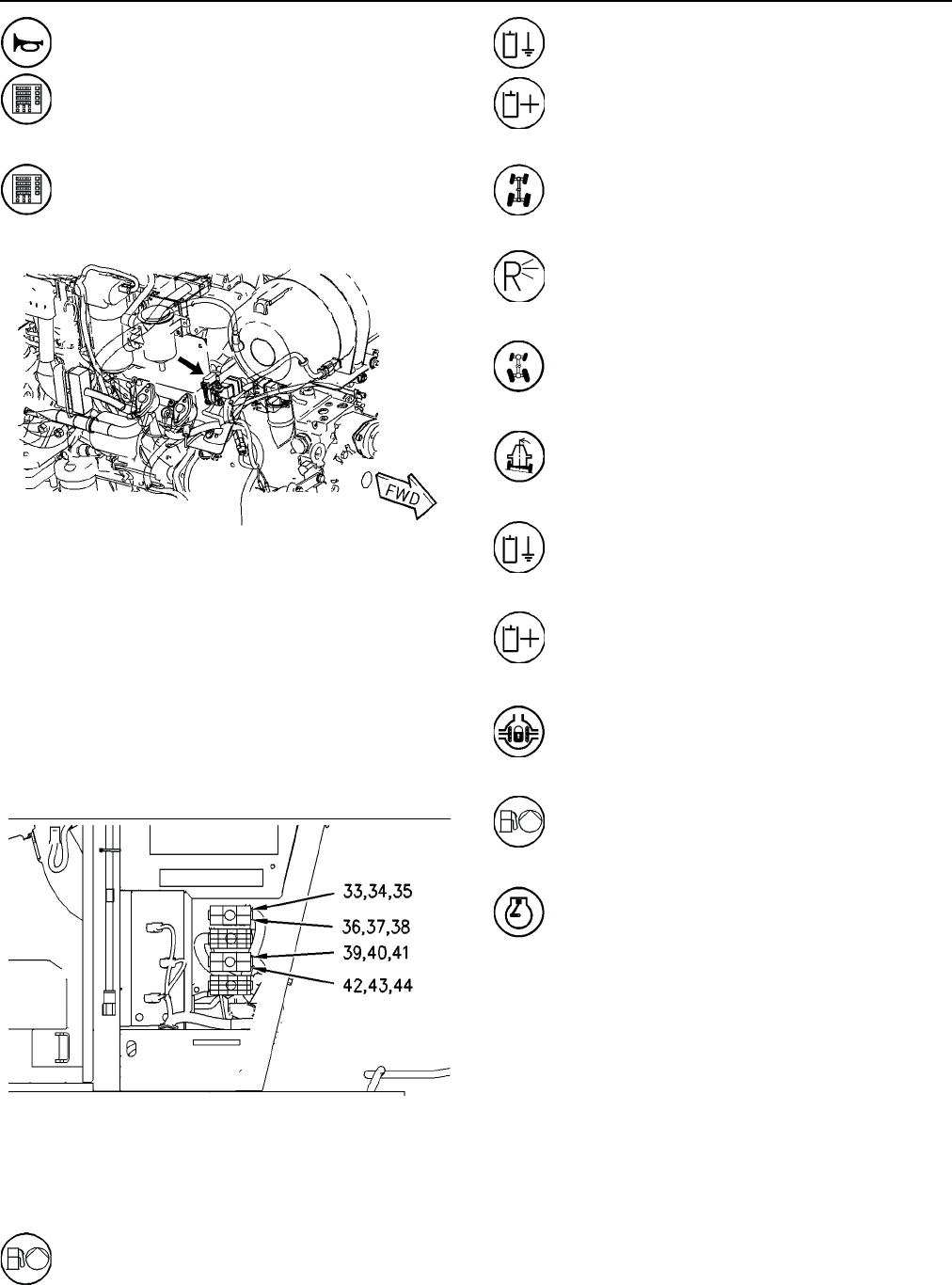
Illustration 270 g01056973
For Tier II machines, the fuse for the fuel pump is
located in the engine compartment next to the circuit
breakers. Remove the protective cover in order to
access the fuse.
Relays
Note: Your machine may not utilize all of the relays that
are listed here. You should only replace these relays
with relays of the same type.
Illustration 271 g00951212
Illustration 271 shows the location of the relays on the fuse
panel. A pictograph is located on the access cover. The
location of the relay matches the location of the pictograph on
the film.
Fuel Pump (33)
Ground for Quick Coupler (34)
Power for Quick Coupler (35)
Crab Steering (36)
Reverse Backup Lights (37)
Circle Steer (38)
Frame Level (39)
Ground for Auxiliary Diverter Valve (40)
Power for Auxiliary Diverter Valve (41)
Differential Lock (42)
Fuel Pump (43)
Engine Solenoid (44)
Indicators and Gauges - Test
Check for broken indicator lights, broken switches or
broken lenses on the instrument panel gauges.
Start the engine. Run the engine until the instrument
panel gauges have stabilized. Check that the
instrument panel gauges are operating correctly.
Stop the engine and perform any necessary repairs
before the machine is operated.
Contents Summary of TH360B Telehandler Operation and Maintenance Manual
- Page 131200243 July 14, 2006 Operation and Maintenance Manual TH360B Telehandler S/N TBH00100 & After Keep this manual with machine at all times.
- Page 2Important Safety Information Most accidents that involve product operation, maintenance and repair are caused by failure to observe basic safety rules or precautions. An accident can often be avoided by recognizing potentially hazardous situations before an accident occurs. A person must be alert to
- Page 331200243 1 Table of Contents Table of Table of Contents Before Operation..................................................30 Operation .............................................................30 Foreword Machine Operating Temperature Range ........30 Literature Information ......................
- Page 431200243 2 Table of Contents Parking ................................................................ 86 Primary Cab Air Filter ...................................115 Stopping the Machine .................................... 86 Secondary Cab Air Filter...............................116 Stopping the
- Page 53 31200243 Table of Contents Rollover Protective Structure (ROPS) and Falling Object Protective Structure (FOPS) -Inspect .... 142 Seat Belt - Inspect ............................................. 142 Seat Belt - Replace ........................................... 143 Stabilizer and Cylinder Bearing
- Page 631200243 4 Table of Contents
- Page 731200243 5 Foreword Foreword Maintenance The maintenance section is a guide to equipment care. Literature Information The Maintenance Interval Schedule (MIS) lists the items to be maintained at a specific service interval. This manual should be stored in the operator's Items without specific interva
- Page 86 31200243 Foreword Contact Information For: • Accident Reporting and Product Safety Publications • Current Owner Updates • Questions Regarding Product Applications and Safety • Standards and Regulations Compliance Information • Questions Regarding Product Modifications Contact: Product Safety and R
- Page 931200243 7 Safety Section Safety Section Safety Messages Illustration 2 g01106084
- Page 108 31200243 Safety Section Illustration 3 g01213315
- Page 1131200243 9 Safety Section Illustration g01213316 Make sure that all of the safety messages are legible. Clean the safety messages or replace the safety messages if you cannot read the words. Replace the illustrations if the illustrations are not legible. When you clean the safety messages, use a clo
- Page 1210 31200243 Safety Section Do Not Operate (1) Do Not Stand Under the Load (2) This safety message is positioned on the panel at the This message is positioned on the side of the boom right side of the operator station. head on both sides of the machine g00931194 Do not operate or work on this equipm
- Page 1331200243 11 Safety Section No Hands (3) Do Not Operate (4) The message is positioned on the side of the number This safety message is located on the front dash in the one boom section on both sides of the machine operator compartment. g00936539 Improper operation or maintenance of the machine could
- Page 1412 31200243 Safety Section Forks (5) Do Not Weld On The ROPS/FOPS This safety message is positioned on the panel at the Structure (6) right side of the operator station. This safety message is positioned behind the seat near the window. g01059274 g01211890 Side loading of the forks may cause prematu
- Page 1531200243 13 Safety Section Crushing Hazard (7) No Hands (8) The message is positioned on the underside of the The message is positioned on the top of stabilizer stabilizer beam on both sides of the machine. cylinders on both sides of the machine. g00930659 g00930870 A crushing hazard exists when rai
- Page 1614 31200243 Safety Section Seat Belt (9) Crushing Hazard (10) This safety message is positioned on the panel at the This message is positioned on the chassis on the right right side of the operator station. side of the machine. g00931188 A seat belt should be worn at all times during machine operati
- Page 1731200243 15 Safety Section Crushing Hazard (11) Engine Coolant (12) This message is positioned on the chassis on the right This safety message is positioned on the coolant tank in the side of the machine. engine enclosure. g00931247 Pressurized system! Hot coolant can cause serious g00930659 burns,
- Page 1816 31200243 Safety Section Avoid Power Lines (13) Low Bridge (14) This safety message is positioned in the operator This safety message is positioned in the operator station on the right side of the window. station on the right side of the window. This message is only located on machines that will b
- Page 1931200243 17 Safety Section Jump Start Cables (15) Ether (16) This safety message is positioned on a bracket next to This safety message is positioned on the intake for the the batteries. air cleaner. g00931020 g00931562 Explosion Hazard! Improper jumper cable connections Explosion hazard! Do not use
- Page 2018 31200243 Safety Section Crushing Hazard (17) Operation (19) This message is located on both sides of the This message is located on the left hand cover at the multipurpose bucket on the top of the bucket. rear of the broom. g00943172 g00984073 No clearance for person in this area during operation
- Page 2131200243 19 Safety Section Crushing Hazard (21) Trap Point (23) This message is located on both sides of the grapple This message is located on both sides of the hitch on bucket. the broom. g00943172 g00984061 No clearance for person in this area during operation. No clearance for person in this are
- Page 2220 31200243 Safety Section Ether (25) This message is located on the side of the valve cover. g00924889 If equipped with an air inlet heater (AIH) for cold weather starting, do not use aerosol types of starting aids such as ether. Such use could result in an explosion and personal injury. Additional
- Page 2331200243 21 Safety Section
- Page 2422 31200243 Safety Section Coolant (1) Auxiliary Hydraulics (3) This message is located on the coolant tank. This message is located on the left side of the boom head. 50% Ethylene Glycol OAM1010 Refill with only 50/50 mixture of ethylene glycol and Illustration 11 g00934458 water. Refer to Operatio
- Page 2531200243 23 Safety Section Alternate Exit (5) Air Conditioner (7) This message is located on the rear window of the cab. On machines that are equipped with an air conditioner, this label is located behind the protection cover at the rear of the door. Illustration 14 g00931915 If the primary exit is
- Page 2624 31200243 Safety Section Machine Security System (9) If equipped, this message is located on the left side of the steering column ahead of the engine start switch. Illustration 20 g00702020 Wear a hard hat, protective glasses, and other protective equipment, as required. Illustration 18 g00951606
- Page 2731200243 25 Safety Section Pressurized Air and Water treatment immediately. Seek treatment from a doctor that is familiar with this type of injury. Pressurized air and/or water can cause debris and/or hot water to be blown out. This could result in personal Containing Fluid Spillage injury. When pre
- Page 2826 31200243 Safety Section Never jump across the starter solenoid terminals in Oils order to start the engine. Unexpected machine movement could result. Hot oil and hot components can cause personal injury. Do not allow hot oil to contact the skin. Also, do not Whenever there are equipment control l
- Page 2931200243 27 Safety Section Do not operate the machine near any flame. Exhaust shields (if equipped) protect hot exhaust components from oil spray or fuel spray in case of a break in a line, in a hose, or in a seal. Exhaust shields must be installed correctly. Do not weld on lines or on tanks that co
- Page 3028 31200243 Safety Section • Outer coverings are chafed or cut. • Wires are exposed. • Outer coverings are ballooning. • Flexible part of the hoses are kinked. • Outer covers have embedded armoring. • End fittings are displaced. Make sure that all clamps, guards, and heat shields are installed corre
- Page 3131200243 29 Safety Section Before Starting Engine Make sure that the machine horn, the backup alarm and all other warning devices are working properly. Operators must have had the proper training and Clear all obstacles from the path of the machine. operators must be capable in all aspects of machin
- Page 3230 31200243 Safety Section Before Operation Before you maneuver the machine, make sure that no personnel are between the machine and the work tools. Clear all personnel from the machine and from the area. Use caution when you change direction of travel. Use Clear all obstacles from the path of the m
- Page 3331200243 31 Safety Section Work Tools Work Tools Use of non approved work tools on Telehandler Use of non approved work tools on Telehandler machines could result in injury or death. machines could result in injury or death. Before installing a work tool on this machine, ensure Before installing a w
- Page 3432 31200243 Safety Section Equipment Lowering with Loss Operator Station of Hydraulic Power Any modifications to the inside of the operator station should not project into the operator space. The addition Before you lower any equipment with loss of hydraulic of a radio, fire extinguisher, and other
- Page 3531200243 33 Safety Section Rollover Protective Structure Other Guards (If Equipped) (ROPS), Falling Object Protective Protection from flying objects and/or falling objects is Structure (FOPS) required for special applications. Logging applications and demolition applications are two examples that Th
- Page 3634 31200243 Safety Section
- Page 3731200243 35 Product Information Section Product Information When the machine is operated on tires, the weight of the intended load determines the maximum height Section above ground. The weight of the intended load also determines the maximum distance that is between the load center of gravity and t
- Page 3836 31200243 Product Information Section 5. If the intended load is heavier than the value in the Example 3 equivalent load zone the lift operation cannot be • The weight of the intended load is 600 units. made. • The boom angle reference is 22 degrees. Examples of Estimating the Lift • The boom exte
- Page 3931200243 37 Product Information Section Specifications Illustration 34 g00855391 Illustration 35 g00855455 Rear View Specifications are shown for basic machines without a work tool on the quick coupler. Table 7 TH360B Machine Overall Height (A) 2590 mm (8 ft 6 inch) Overall Length (B) 6385 mm (20 ft
- Page 4038 31200243 Product Information Section Intended Use Identification Information This vehicle is classified either as: • A self-propelled variable reach truck (Telehandler) as Plate Locations and Film Locations defined in "ISO 3691-2" and "EN 1459:1998" • An agricultural tractor when meeting the requ
- Page 4131200243 39 Product Information Section Serial Number If the machine is equipped with the plate for the Caterpillar products such as engines, transmissions and European Union, this plate will be attached to the PIN major attachments that are not designed for an operator plate. Several pieces of info
- Page 4240 31200243 Product Information Section ROPS/FOPS Film This safety message is positioned behind the seat on the rear window. Illustration 44 g01015547 This plate is located on the control group for the MSS. The control group is located in the engine compartment. Illustration 43 g01211890 Structural
- Page 4331200243 41 Product Information Section Illustration 47 g00937218 The following information is stamped on the plate: “Model" • “Model”___________________________________ • "Homologation number"______________________ • "PIN"_____________________________________ • "Allowed total weight"_______________
- Page 4442 31200243 Product Information Section Emissions Certification Film Note: This information is pertinent in the United States and in Canada. If equipped, the EPA/EU Emission Certification Film is located on the side of the engine block. A typical example is shown. Il Illustration 49 g01148857
- Page 4531200243 43 Operation Section Operation Section Daily Inspection Before Operation Hot oil and hot components can cause personal injury. Mounting and Dismounting Do not allow hot oil or hot components to contact skin. At operating temperature, the engine coolant is hot and under pressure. Steam can c
- Page 4644 31200243 Operation Section Perform the following procedures on a daily basis. • Backup Alarm - Test • Braking System - Test • Cooling System Coolant Level - Check • Engine Oil Level - Check • Fuel System Water Separator - Drain • Fuel Tank Water and Sediment - Drain • Indicators and Gauges - Test
- Page 4731200243 45 Operation Section Machine Operation Seat Adjustment Alternate Exit The rear window can be used as an alternate exit on machines which are equipped with an enclosed cab. If the primary exit is blocked, exit the machine through the rear window. Illustration 52 g00950445 Fore/aft Lever (1)
- Page 4846 31200243 Operation Section Air Suspension (If Equipped) Seat Belt Adjustment for Non-Retractable Seat Belts Adjust both ends of the seat belt. The seat belt should be snug but comfortable. Lengthening the Seat Belt Illustration 53 g00950464 Weight Adjustment Switch (4) - Adjust the seat height wi
- Page 4931200243 47 Operation Section Shortening the Seat Belt Releasing The Seat Belt Illustration 56 g00100713 Illustration 58 g00100717 Pull up on the release lever. This will release the seat 1. Fasten the seat belt. Pull out on the outer belt loop in belt. order to tighten the seat belt. 2. Adjust the
- Page 5048 31200243 Operation Section Releasing The Seat Belt Illustration 60 g00039113 Push the release button on the buckle in order to release the seat belt. The seat belt will automatically retract into the retractor. Extension of the Seat Belt When using retractable seat belts, do not use seat belt ext
- Page 5131200243 49 Operation Section Operator Controls (Side Console) Illustration 61 g01212209 Note: Your machine may not be equipped with all of the Roof Wiper/Washer (6) controls that are described in this topic. Roof Wiper/Washer - Push the top of switch Fan Control (1) in order to operate the window w
- Page 5250 31200243 Operation Section • Boom retract • Quick coupler • Auxiliary actuators • Stabilizers When the machine is driven on public roads, the bottom of the switch should be pressed. This will help prevent accidental movement of hydraulically controlled components. To allow operation of hydraulic
- Page 5331200243 51 Operation Section Operator Controls Illustration 62 g01213390 ( (1) Quick coupler control (13) Joystick control (2) Transmission neutralizer control (14) Adjustable armrest (3) Steering mode control (15) Side console (4) Frame leveling control (16) Interior light (5) Left stabilizer cont
- Page 5452 31200243 Operation Section Transmission Neutralizer Control (2) If the transmission neutralizer control switch is in the ON position and the service brake control pedal is pressed, the transmission will shift into NEUTRAL. When the service brake control pedal is released it will take a short peri
- Page 5531200243 53 Operation Section Machines without Steer Sensors 1. In a static position, select circle steer mode. By using your eyes, align the rear wheels to a straight position. 2. Select two-wheel steer mode. By using your eyes, align the front wheels to a straight position. 3. Select your desired
- Page 5654 31200243 Operation Section 2. Turn the steering wheel until the left rear wheel is in line The frame leveling control is used to level the machine with the side of the machine. when the machine is on an uneven surface. The frame leveling control can cause the frame to tilt to the left or to the r
- Page 5731200243 55 Operation Section Left Stabilizer (5) (if equipped) - This is a 5. Push the left of switch (6) and hold the switch in spring return switch with three positions. Push order to lower the right stabilizer. Observe the area the right of the switch in order to raise the left around the right
- Page 5856 31200243 Operation Section Fog Lights (8) Type A Control Arrangement (Single Thumb Wheel) Fog Lights - Push the right side of switch in order to turn on the fog lights. Push the left side of switch in order to turn off the fog lights. Hazard Flashers (9) Hazard Flashers - Push the right side of s
- Page 5931200243 57 Operation Section Quick Coupler (Tilt Backward) - Push The speed of the boom extend and boom retract is joystick control (13) to the left in order to tilt the governed by the amount of movement of thumb wheel quick coupler backward. When joystick (13B). control (13) is released, the joys
- Page 6058 31200243 Operation Section Quick Coupler (Tilt Forward) - Push the • Quick coupler (tilt backward) joystick control to the right in order to tilt the For smooth operation, first increase the engine speed quick coupler forward. When the joystick from low idle. Then move joystick control (13) slowl
- Page 6131200243 59 Operation Section joystick control (13) is released, the joystick control will The speed of the following functions is governed by the return to the HOLD position. amount of movement of the joystick control and engine Boom Lower - Push joystick control (13) speed: forward in order to low
- Page 6260 31200243 Operation Section operate an actuator for a work tool in the negative direction. Switch (13E) is not operated proportionally. Illustration 80 g01213466 Boom Raise - Pull joystick control (13) Illustration 81 g01017263 backward in order to raise the boom. When the joystick control is rele
- Page 6331200243 61 Operation Section Lift the armrest in order to adjust the armrest. Parking Brake Disengaged - Pull back lever (17) and In order to adjust the angle of armrest, rotate knob pull lever (17A) in order to release the latch. Lower (14A). To increase the angle of the armrest, turn the lever (1
- Page 6462 31200243 Operation Section differential lock, release pressure from accelerator transmission speed is opposite the line. All four pedal (18) and release differential lock control. speeds can be selected for forward travel. The first three speeds can be selected for reverse travel. Select the prop
- Page 6531200243 63 Operation Section transmission control to the next lowest gear. Do not automatically shift the transmission between the lowest skip gears when you down shift. Continue to shift gears to the highest gear that has been selected, through the gears in this way as the conditions are based on
- Page 6664 31200243 Operation Section Steering Column Tilt Control (27) Note: MSS will not shut down the machine after the machine has started. Move lever (27) upward in order to unlock the steering column. Pivot the steering column to the desired Security Management position. Move lever (27) downward in or
- Page 6731200243 65 Operation Section OFF - Turn the battery disconnect switch key • Limited Free Axle counterclockwise in order to shut off the entire • Locked Axle electrical system. Free Axle The battery disconnect switch and the engine start This mode is equivalent to a machine that is operating switch
- Page 6866 31200243 Operation Section Use the following procedure in order to move the install the boom cylinder lock. Clean the area, if machine to a safe location. necessary. 1. Ensure that the transmission speed control is in 3. Check that the cylinder lock is the correct type for the NEUTRAL position. y
- Page 6931200243 67 Operation Section switch key. Attach a "Do Not Operate" or a similar Operation Information warning tag to the joystick control. Removal Note: Follow the same mounting and dismounting guidelines that are detailed in the installation section. Do not operate or work on this machine unless t
- Page 7068 31200243 Operation Section machine in order to disengage the load from the work tool. Operate the boom smoothly in order to avoid damaging or dislodging the load. Do not move the machine while the boom is raised or while the boom is extended. If it is necessary to reposition the machine, lower an
- Page 7131200243 69 Operation Section Changing Speed and Direction When you are travelling uphill, select a lower gear when the engine speed starts to fall. Drive the machine in the gear that will allow the required speed to be maintained. Do not allow the torque converter to slip and do not allow the engin
- Page 7270 31200243 Operation Section Illustration 96 g00975278 Illustration 98 g00975388 Left quick coupler pin 4. Extend the boom slowly until the quick coupler 7. Check the positions of the pins on both sides of the tubes contact the carriage. Raise the boom until the quick coupler. Both quick coupler pi
- Page 7331200243 71 Operation Section Illustration 102 g00975278 Illustration 100 g00975363 4. Lower the boom and tilt the quick coupler forward 4. Extend the boom slowly until the quick coupler until the carriage is on the ground. If necessary, tubes contact the carriage. Raise the boom until the block the
- Page 7472 31200243 Operation Section 2. Remove the retaining pin and remove pin (3). 3. Lower the boom and tilt the quick coupler forward until the carriage is on the ground. If necessary, block the carriage in order to prevent the carriage from moving when the carriage is disengaged from the quick coupler
- Page 7531200243 73 Operation Section keeping the quick coupler at the selected angle when the boom is raised or lowered. Illustration 111 g00832856 Illustration 108 g00832852 10. Raise the load carefully. When you are sure that the machine is stable, tilt the quick coupler 6. Ensure that the forks are spre
- Page 7674 31200243 Operation Section Proceed with caution when you approach the maximum angle and/or extension indicated by the load chart. If you are not sure that the machine is stable, retract the boom. Lower the load to the travel position. Move the machine closer to the load placement location. If the
- Page 7731200243 75 Operation Section Make sure that the work tool that is being used is appropriate for the work that is being performed. Exceeding the machine limits will reduce the service life of the machine. Refer to Operation and Maintenance Manual, "Caterpillar Approved Work Tools" for additional inf
- Page 7876 31200243 Operation Section When you attach work tools that require hydraulic All Caterpillar approved carriages that are used on connections, extend the boom by approximately 1 m (3 these machines can be installed directly to the quick ft) after installing the work tool onto the quick coupler. co
- Page 7931200243 77 Operation Section Forks that have been used for any of the applications that must be connected to the machine hydraulic that are listed above must be removed from the system. The jaws of the bucket grip the load. machine. The forks must be destroyed. For the best operator visibility, tra
- Page 8078 31200243 Operation Section Multipurpose Buckets Double Thumb Wheel Illustration 126 g01037342 Typical multipurpose bucket Multipurpose buckets are equipped with a cutting edge. Multipurpose buckets are equipped with hydraulic cylinders that must be connected to the machine hydraulic system. The j
- Page 8131200243 79 Operation Section damage to surrounding structures and materials could Reference the correct load chart and do not exceed the result. machine capacities. Extremely cold temperatures could cause a load to be Use only approved lifting equipment with a current frozen to the ground. Free the
- Page 8280 31200243 Operation Section Picking up the Hopper Broom Position the machine square to the hopper. Extend and lower the boom. The forks must enter the pockets of the hopper cleanly. The forks must be fully engaged with the pockets of the hopper. Illustration 135 g01015331 Refer to Operation and Ma
- Page 8331200243 81 Operation Section When a warning category 2S occurs, the action lamp Circle Steer (7) - This indicator is illuminated flashes red and there is a constant audible alarm. In when circle steer mode is selected. order to prevent severe damage to components, the operator is required to change
- Page 8482 31200243 Operation Section equipped. Refer to Illustration 139. Refer to "Longitudinal Stability Indicator" for more information. Longitudinal Stability Indicator Operating the machine beyond its stability limit could result in a tip over or failure of the work tool. Check the proposed lift with
- Page 8531200243 83 Operation Section machine stability. The variable gauge is located in the lamp will be illuminated. Refer to Operation and center of the display panel. Maintenance Manual, "Longitudinal Stability Indicator As the load on the machine increases, the indicator System - Test" for more inform
- Page 8684 31200243 Operation Section Cab Door Engine Starting Unlock the cab door. Engine Starting Note: The key for the cab door is the same key as the engine start key. Diesel engine exhaust contains products of combustion which may cause personal injury. Always start and operate the engine in a well ven
- Page 8731200243 85 Operation Section 6. Turn the engine start switch key (3) to the RUN 2. If the temperature is below the preset limit, position in order to initialize the machine. The indicator (4) will illuminate on the instrument panel. machine will run a self test that must be completed 3. When indica
- Page 8886 31200243 Operation Section Parking Stopping the Machine NOTICE Park on a level surface. If it is necessary to park on a grade, block the wheels securely. Engage the parking brake. Do not engage the secondary brake while the machine is moving, unless the primary service brakes fail. Illustration 1
- Page 8931200243 87 Operation Section 6. Inspect the engine compartment for debris. Clean Refer to Operation and Maintenance Manual, out any debris and any paper in order to avoid a "Specifications" for the basic dimensions and the fire. weights for shipping a standard machine. 7. Turn the key for the batte
- Page 9088 31200243 Operation Section Lifting and Tying Down the Machine 6. Engage the parking brake and move the transmission control to the NEUTRAL position. 7. Ensure that the boom is fully retracted. Ensure that the boom is lowered. A machine may shift if improper procedures or 8. Stop the engine and re
- Page 9131200243 89 Operation Section at least 150 percent of the gross weight of the towed disabled machine if the operator can control the machine. This pertains to towing a disabled machine steering and/or braking. from mud and to towing a machine on a grade. Use an observer in a safe position in order t
- Page 9290 31200243 Operation Section Types of Towing Hitches Your machine may be equipped with a number of Towed attachments which exceed the weights which different types of towing hitch. Refer to the are shown above must be equipped with a suitable type appropriate section that is listed below for a of b
- Page 9331200243 91 Operation Section the original position. When the locking mechanism is Engine Starting (Alternate engaged, return pin (6) to the original position. In order to connect the attachment for towing, remove pin Methods) (8). Align the machine and the tow eye for the attachment. Reverse the ma
- Page 9492 31200243 Operation Section This machine has a 12 volt starting system. Use only the 11. Finally, connect the other negative end of the jump same voltage for jump starting. Use of a welder or higher start cable to the frame of the stalled machine. Do voltage damages the electrical system. not conn
- Page 9531200243 93 Operation Section Equipment Lowering with Loss of Procedure for Draining Hydraulic Tank Hydraulic Power Hot oil and hot components can cause personal injury. Do not allow hot oil or hot components to contact skin. Lowering the boom with the engine stopped can cause personal injury or dea
- Page 9694 31200243 Operation Section Illustration 145 g01205670 Hydraulic tank filler cap SLE3000-UP 2. Lift latch (5), and turn the latch counterclockwise in order to relieve the pressure in the hydraulic Illustration 01205716 system. Remove hydraulic tank filler cap (6). 1. Locate the rear cover on the b
- Page 9731200243 95 Operation Section 8. Start the engine. Raise and lower the boom. Extend and retract the boom approximately 300 mm (12 inch). 9. Position the boom to the fully retracted position. Position the boom to the fully lowered position. 10. Remove the hydraulic tank filler cap. Add the 12 L (3.17
- Page 9896 31200243 Operation Section 3. Locate control valve (14). Refer to Illustration 155. 1. Fully raise the boom and fully lower the boom. 4. Measure the distance from the head of adjustment 2. Repeat this procedure three times in order to purge screw (16) to the top of locknut (15). Completely the ai
- Page 9931200243 97 Maintenance Section Maintenance Section Maintenance Access Access Doors and Covers Illustration 172 g01206261 In order to open protection cover (4) on the left side of the machine, unlock lock (3) and turn lock (5) counterclockwise. Then, pull latch (2) outward. Open the protection cover
- Page 10098 31200243 Maintenance Section Tire Pressure Personal injury can result from improper tire inflaton. A tire blowout or rim failure can result from improper or misused equipment. Use a self-inflating chuck and stand behind the tread when inflating a tire. Proper inflating equipment, and training in
- Page 10131200243 99 Maintenance Section Tire Inflation Pressure Adjustment recommendations, may result in unsafe condition regarding stability. The tire pressure in a warm shop area 18° to 21 °C (65° to 70°F) will significantly change when you Wheel and Tire Installation move the machine into freezing tempe
- Page 102100 31200243 Maintenance Section Lubricant Viscosities and Refill Capacities Lubricant Viscosities The proper oil viscosity grade is determined by the minimum outside ambient temperature. This is the temperature when the machine is started and while the machine is operated. In order to determine the
- Page 10331200243 101 Maintenance Section Table 13 Lubricant Viscosities for Ambient Temperatures °C °F Compartment or System Oil Type and Classification Oil Viscosities Min Max Min Max SAE 0W-20 -40 10 -40 50 SAE 0W-30 -40 30 -40 86 Cat DEO Multigrade SAE 0W-40 -40 40 -40 104 Cat DEO SYN SAE 5W-30 -30 30 -2
- Page 104102 31200243 Maintenance Section Capacities (Refill) Table 16 (Table 16, contd) APPROXIMATE REFILL CAPACITIES APPROXIMATE REFILL CAPACITIES Compartment or Imp Compartment or Imp Liter US gal Liter US gal System gal System gal Front Axle Differential(1) 10.5 2.8 2.3 Cooling System (Total capacity wit
- Page 10531200243 103 Maintenance Section Grease Points Identification Refer to the Operation and Maintenance Manual, "Maintenance Interval Schedule" for a specific sampling location and a service hour maintenance interval. Consult your Caterpillar dealer for complete information and assistance in establishi
- Page 106104 31200243 Maintenance Section Maintenance Interval Schedule Every 10 Service Hours or Daily Backup Alarm - Test................................................ 106 Ensure that all safety information, warnings, and Braking System - Test............................................. 114 instructions
- Page 10731200243 105 Maintenance Section Every 500 Service Hours or 6 Months Every 2000 Service Hours or 2 Years Boom Chain Tension - Check/Adjust ...................... 108 Engine Valve Lash - Check .................................... 129 Boom Cylinder Pin - Lubricate .................................110
- Page 108106 31200243 Maintenance Section Axle Breathers - Clean/Replace Turn the engine start switch to the ON position in order to perform the test. 1. Park the machine on level ground. Fully retract the Apply the service brake. Move the transmission control boom and fully lower the boom. Move the lever to
- Page 10931200243 107 Maintenance Section Belt - Inspect/Replace 4. Remove the retaining bolts for the fan guard. Slide the guard out of the engine enclosure Inspect Note: If a new belt is installed, check the film on the belt tensioner (2) after 30 minutes of operation. A belt is considered to be used after
- Page 110108 31200243 Maintenance Section Boom Chain - Inspect/ 4. Install the cover on the rear of the boom. Lubricate Check and Adjust the Chain Tension Note: The information that follows will only relate to 1. Slacken the extension chain and the retraction machines that have a three-section boom. chain sl
- Page 11131200243 109 Maintenance Section Measure the Chain for Wear Nominal pitch of the link equals 25.4 mm (1 inch). Nominal height of the plate equals 24.1 mm (0.95 inch). 1. Fully retract the boom. Position the boom horizontally. 2. Extend the boom by 2 m (6 ft 7 inch) or extend the boom to the section
- Page 112110 31200243 Maintenance Section Boom Cylinder Pin - Lubricate Illustration 190 g00950677 Illustration 187 g00951662 Lubricate the pivot shaft for the boom through the lubrication fitting. The lubrication fitting is located on top There is a boom raise cylinder under the boom. of the pivot shaft for
- Page 11331200243 111 Maintenance Section Boom Wear Pad Clearance - Inspect/Adjust The clearance between the wear pads and the boom section should be checked at more frequent intervals when the machine is operated in severe conditions. Note: Sand or grit particles can cause accelerated wear to the wear pads.
- Page 114112 31200243 Maintenance Section 7. Measure clearances (4) between the rear wear pads and the top of the boom sections. 8. The clearance at each location must not exceed 1.5 mm (0.06 inch). If the clearances are excessive, adjustments must be made. Adjustment Note: The bolts that secure different we
- Page 11531200243 113 Maintenance Section your own repairs, consult your Caterpillar dealer for the recommended repair techniques. Illustration 200 g00858059 7. Extend the boom and lower the work tool to the Illustration 201 g00861901 ground. Lower the boom to the ground and fully Main frame and support crad
- Page 116114 31200243 Maintenance Section Illustration 202 g00836172 Illustration 204 g00836174 Stabilizer and rollover protection structure Pivot pins and anchor points Lower stabilizers (2) until the stabilizer pads are Inspect all pivot pins and inspect all anchor points for touching the ground. Inspect e
- Page 11731200243 115 Maintenance Section 4. If the machine is equipped with a power shift transmission, move the transmission control lever in the following pattern: If the machine moved while testing the service brakes, contact your Caterpillar dealer. • SECOND GEAR FORWARD Have the dealer inspect, and if
- Page 118116 31200243 Maintenance Section 1. The primary cab air filter is located behind 3. If the air filter is not damaged, clean the air filter protection cover (3) on the left side of the cab. In with pressurized air. The maximum air pressure order to open the protection cover, unlock lock for cleaning
- Page 11931200243 117 Maintenance Section Cooling System Coolant - Change Personal injury can result from hot coolant, steam and alkali. At operating temperature, engine coolant is hot and under pressure. The radiator and all lines to heaters or the engine contain hot coolant or steam. Any contact can cause
- Page 120118 31200243 Maintenance Section Cooling System Coolant Level - Check Personal injury can result from hot coolant, steam and alkali. At operating temperature, engine coolant is hot and under pressure. The radiator and all lines to heaters or the engine contain hot coolant or steam. Any contact can c
- Page 12131200243 119 Maintenance Section Cooling System Coolant • Place the sample in the mailing tube immediately after obtaining the sample in order to avoid Sample (Level 1) - Obtain contamination. NOTICE • Never collect samples from the drain for a system. Submit the sample for Level 1 analysis. Always
- Page 122120 31200243 Maintenance Section Cooling System Pressure Cap Cooling System Water - Clean/Replace Temperature Regulator Replace Personal injury can result from hot coolant, steam and alkali. Personal injury can result from hot coolant, steam and At operating temperature, engine coolant is hot and al
- Page 12331200243 121 Maintenance Section cooling system coolant is drained to a level that is Differential Oil - Change below the water temperature regulator housing. NOTICE Care must be taken to ensure that fluids are contained during performance of inspection, maintenance, testing, adjusting and repair of
- Page 124122 31200243 Maintenance Section Front Axle Differential Differential Oil Level - Check NOTICE Care must be taken to ensure that fluids are contained during performance of inspection, maintenance, testing, adjusting and repair of the product. Be prepared to collect the fluid with suitable containers
- Page 12531200243 123 Maintenance Section Front Axle Differential Illustration 230 g01014887 Rear axle differential Illustration 229 g01014889 1. Clean the area around combined level and filler plug (2) for the front differential. Remove combined level and filler plug (2) and check that the oil is level with
- Page 126124 31200243 Maintenance Section Drive Shaft Spline - Lubricate Drive Shaft Universal Joint Bolts - Check NOTICE Apply lubricant to the fittings with a hand operated grease gun only. Use of pressure operated lubricating equipment damages the seals. Illustration 234 g00856592 Locations of the Univers
- Page 12731200243 125 Maintenance Section Engine Air Filter Primary Element - Clean/Replace Note: The primary air filter element can be used up to three times if the element is properly cleaned and inspected. Replace the primary air filter element if the element has been in service for 500 hours or six month
- Page 128126 31200243 Maintenance Section NOTICE Inspecting the Primary Air Filter Do not clean the air filter elements by bumping or Elements tapping. This could damage the seals. Do not use elements with damaged pleats, gaskets, or seals. Damaged elements will allow dirt to pass through. Engine damage coul
- Page 12931200243 127 Maintenance Section and mark the primary air filter element. Include the 6. Cover the air inlet opening. Clean the inside of the following information: air cleaner housing. • Date of cleaning 7. Uncover the air inlet opening. Install a new secondary element. • Number of cleanings 8. Ins
- Page 130128 31200243 Maintenance Section Engine Oil and Filter - Change Hot oil and hot components can cause personal injury. Do not allow hot oil or hot components to contact skin. NOTICE Care must be taken to ensure that fluids are contained during performance of inspection, maintenance, testing, adjustin
- Page 13131200243 129 Maintenance Section Illustration 249 g01081070 9. Remove filler cap (4) and fill the crankcase with new oil. 10. Refer to Operation and Maintenance Manual, "Lubricant Viscosities" for more information on the Illustration 246 g00975860 type of oil that is required. Refer to Operation and
- Page 132130 31200243 Maintenance Section 2. Fully retract the boom and fully lower the boom. Move the transmission control to the NEUTRAL position and engage the parking brake. Shut off the Be sure the engine cannot be started while this engine. maintenance is being performed. To prevent possible injury, do
- Page 13331200243 131 Maintenance Section Illustration 252 g00952220 Illustration 253 g00952220 1. To check the oil level on the final drive, position the Fully retract the boom and fully lower the boom. Move machine on level ground. Position the plug for the the transmission control to the NEUTRAL position
- Page 134132 31200243 Maintenance Section Fork Leveling Cylinder Pin - Lubricate Illustration 256 g01013692 The frame leveling cylinder is located at the front right of the machine. Lubricate the frame leveling cylinder pin through the fitting on the top mounting point. Fuel System - Prime 1. Turn the engine
- Page 13531200243 133 Maintenance Section Fuel System Secondary Filter 6. Internally, remove the fuel filter plug from the secondary fuel filter. Remove any sediment from Replace the sediment chamber. Reinstall the plug. Reinstall both the cap and the nut onto the secondary fuel filter. 7. Valve (2) is locat
- Page 136134 31200243 Maintenance Section NOTICE NOTICE Care must be taken to ensure that fluids are contained Care must be taken to ensure that fluids are contained during performance of inspection, maintenance, testing, during performance of inspection, maintenance, testing, adjusting and repair of the pro
- Page 13731200243 135 Maintenance Section 9. Prime the fuel system. Refer to Operation and 3. Lift latch (5) and turn the fuel filler cap Maintenance Manual, "Fuel System - Prime" for counterclockwise. This will release the fuel filler cap. further instructions. 4. Remove fuel filler cap (6) and inspect the
- Page 138136 31200243 Maintenance Section 1. Loosen the fuel tank drain plug. Do not remove Note: Your machine may not utilize all of the fuses the fuel tank drain plug. Allow the water and the that are listed here. You should only replace these sediment to drain into a suitable container and fuses with fuse
- Page 13931200243 137 Maintenance Section Frame Level (1) - 10 AMP Work Light (15) -10 AMP Differential Lock (2) - 10 AMP Rear Work Lights (16) - 10 AMP Front Window Wiper (3) - 10 AMP Engine Start (17) - 10 AMP Rear Window Wiper (4) -15 AMP Hazard Flashers (18) - 10 AMP High Speed Air Conditioner Blower (5)
- Page 140138 31200243 Maintenance Section Horn (30) -10 AMP Ground for Quick Coupler (34) Electrical Monitoring System (31) - 15 AMP Power for Quick Coupler (35) Electrical Monitoring System (32) - 20 AMP Crab Steering (36) Reverse Backup Lights (37) Circle Steer (38) Frame Level (39) Ground for Auxiliary Di
- Page 14131200243 139 Maintenance Section Longitudinal Stability Indicator 4. After the self tests are completed, the machine will test the longitudinal stability indicator system. - Calibrate a. If the test is successful, the gauge will function in the manner that was described in Operation and Maintenance
- Page 142140 31200243 Maintenance Section If metals are found in the filter element, a magnet can be If the machine moves during the parking brake test, used to differentiate between ferrous metals and then perform the adjustment procedure again. If you run nonferrous metals. out of adjustment on the parking
- Page 14331200243 141 Maintenance Section Fully raise the boom and lubricate the boom retraction chain 4. Use compressed air to remove dust and other roller through one fitting. Access is through a hole on the left debris from the radiator core and the condenser side of the boom. core. 5. Tilt back the conde
- Page 144142 31200243 Maintenance Section Rollover Protective Structure Note: Apply oil to the bolts before you install the bolts. Failure to apply oil can result in improper bolt torque. (ROPS) and Falling Object 3. Install the windshield washer reservoir, and install Protective Structure (FOPS) - the two b
- Page 14531200243 143 Maintenance Section Seat Belt - Replace Tire Inflation - Check Within three years of the date of installation or within five years of the date of manufacture, replace the seat belt. Replace the seat belt at the date which occurs first. A date label for determining the age of the seat Pe
- Page 146144 31200243 Maintenance Section Transmission and Hydraulic System Oil - Change Hot oil and hot components can cause personal injury. Do not allow hot oil or hot components to contact skin. NOTICE Care must be taken to ensure that fluids are contained during performance of inspection, maintenance, t
- Page 14731200243 145 Maintenance Section 5. Fill the hydraulic tank with new oil and install the hydraulic tank filler cap. Clean up any oil that has spilled. Refer to Operation and Maintenance Manual, "Lubricant Viscosities" and Operation and Maintenance Manual, "Capacities (Refill)" for additional informa
- Page 148146 31200243 Maintenance Section 4. Remove oil filter (7). After you remove the oil filter, discard the oil filter. The oil filter will contain oil. 5. Clean the housing base for the oil filter. Make sure that all of the old filter seal has been removed. 6. Apply a thin film of clean oil to the seal
- Page 14931200243 147 Maintenance Section Maintenance Manual, "Lubricant Viscosities" and 3. Install the clean breather, and reattach the hose. Operation and Maintenance Manual, "Capacities Tighten the hose clamp. (Refill)" for additional information. 3. Close the protection cover. Turbocharger - Inspect If
- Page 150148 31200243 Maintenance Section Window Washer Reservoir -Fill Windows - Clean NOTICE Use Caterpillar nonfreezing window washer solvent or a commercially available windshield washer fluid in order to prevent freezing of the windshield washer system. Illustration 304 g00856748 Use commercially availa
- Page 15131200243 149 Maintenance Section To perform a proper inspection, the forks must be Yearly Inspection thoroughly cleaned. It is impossible to inspect the forks properly if the work tool is dirty. Inspect the forks before the forks are attached to the machine. Perform the yearly inspection for the for
- Page 152150 31200243 Maintenance Section Illustration 307 g01001968 Illustration 309 g01001990 6. Check markings (K) for readability. Renew the 4. Check the difference in the height of the tip of one markings if the markings are not legible. fork against the height of the tip of the other fork when the fork
- Page 15331200243 151 Maintenance Section Bucket Wear Plates Personal injury or death can result from falling bucket. When working under or around the bucket or linkage, with the bucket raised, proper support must be provided for the bucket and/or the linkage. Replace the wear plates before damage to the bot
- Page 154152 31200243 Maintenance Section
- Page 15531200243 153 Reference Information Section Reference Information Section Approved Work Tools Use of non approved work tools on Telehandler machines could result in injury or death. Before installing a work tool on this machine, ensure that it is approved by Caterpillar and that a Caterpillar load ch
- Page 156154 31200243 Reference Information Section Table 23 Approved Work Tools Part Number Work Tool 215-4350 Carriage (Standard) 174-7731 Carriage (Wide) 231-3229 Rotating Carriage (Standard) 227-5748 Rotating Carriage (Wide) 215-7963 Fork Gp (Pallet 1070 mm) 252-1454 Fork Gp (Pallet 1070 mm) 145-5346 For
- Page 15731200243 155 Index Index A D Access Doors and Covers.................................................. 97 Daily Inspection.................................................................. 43 Additional Messages .......................................................... 20 Differential Oil - Change.
- Page 158156 31200243 Index Fuses and Relays - Replace ............................................ 136 Hydraulic Quick Coupler ............................................... 69 Fuses .......................................................................... 136 Load Handling and Stacking...................
- Page 15931200243 157 Index R Transmission and Hydraulic System Tank Breather - Clean................................................................................ 147 Radiator Core - Clean ...................................................... 141 Transportation Information ...............................
- Page 160158 31200243 Index
- Page 161JLG Industries, Inc. TRANSFER OF OWNERSHIP To Product Owner: If you now own but ARE NOT the original purchaser of the product covered by this manual, we would like to know who you are. For the purpose of receiving safety-related bulletins, it is very important to keep JLG Industries, Inc. updated wi
- Page 162
- Page 163Product and Dealer Information Note: For product identification plate locations, see the section "Product Identification Information" in the Operation and Maintenance Manual. Delivery Date: ____________________ Product Information Model:_______________________________________________________________
- Page 164Manufactured by JLG under license from Caterpilla